Connection of optional shunt releases
In some countries, automatic AC shutdown is required in the event of a fault. A shunt release can be connected to the wallbox for this purpose.
Connecting the shunt release
- Install shunt release in the house connection box. Follow the manufacturer's installation instructions.
- Route the cable between the wallbox and shunt release.
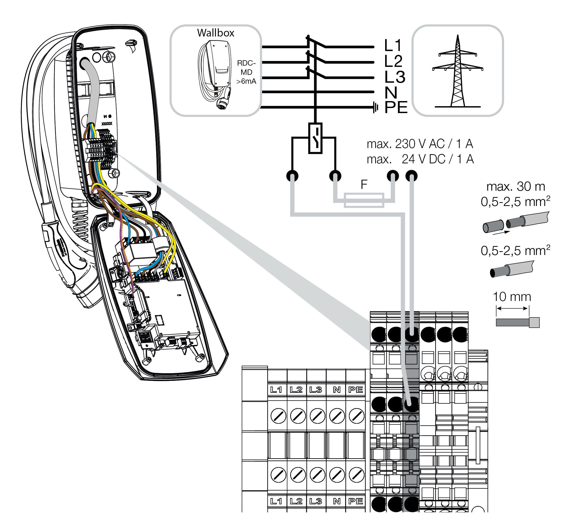
Note connection data for shunt trip input.
- Clamping area rigid / flexible 0.5- 2.5 mm²
- Clamping area with core end sleeves 0.5 - 2.5 mm² DANGER
Risk of death due to electrical shock and discharge!
If the cable is not kept reliably separate from active electrical equipment, touchable parts may be live. As a result, people may be seriously injured or killed by electric shock.
When routing and connecting the cable, keep it reliably separate from active electrical equipment.
- Use a suitable to tool to cut the required cable inlet out of the wallbox. Cable inlets are located on the rear, bottom and top.
- Insert the appropriate membrane cable entry (included in the scope of delivery) into the respective cable inlet.
For cable inlet on the top or bottom: Use membrane cable entries with strain relief.
For cable inlet on the rear: Use membrane cable entries without strain relief. - Insert the cables into the wallbox. To do this, a hole must be pierced in the membrane.
INFO

To prevent rainwater from entering, the hole in the membrane should not be any larger than the cables.
- Strip the cable.
- Strip 10 mm of insulation from the wires.
- Connect cable to wallbox terminal according to terminal labelling.
INFO
The potential-free contact (normally open contact) can be loaded to max. 230 V AC / 24 V DC / 1 A.
- Connect cable to shunt release.
- Wallbox connected to shunt release.