The connection and control panel
Battery Management System (BMS) – control elements
1 | DC - (negative DC input) |
2 | DC + (positive DC input) |
3 | OUT (communication output for connection between battery towers/parallel connection) |
4 | Control panel (HMI – Human Machine Interface) |
5 | ON/OFF (On/Off switch) |
6 | INV (communication connection to inverter) |
7 | PE (protective conductor connection) |
8 | IN (communication input for connection between battery towers/parallel connection) |
9 | Fuses/break switches for battery system |
The control panel
1 | The SoC status display is a visual indication of the system’s current state of charge (SoC). Each LED represents 20% of the battery capacity. |
2 | Function currently being prepared |
3 | Only activate First Tower at the first tower, which is directly connected to the inverter. If there are several towers, First Tower must be deactivated for the other towers. |
4 | Last Tower marks the last tower in the system. Only activate Last Tower at the last tower. If there are several towers, Last Tower must be deactivated for the remaining towers. |
5 | Indicates the communication status with the inverter. LED green: Communication OK / LED off: Communication fault. |
6 | Status display alarm. If an LED is lit up, there is an error. |
7 | Numbers 1-9 correspond to the modules, running from top to bottom. If the modules are working properly, the LEDs are off. If a module fails, the corresponding number lights up orange. |
SoC status display
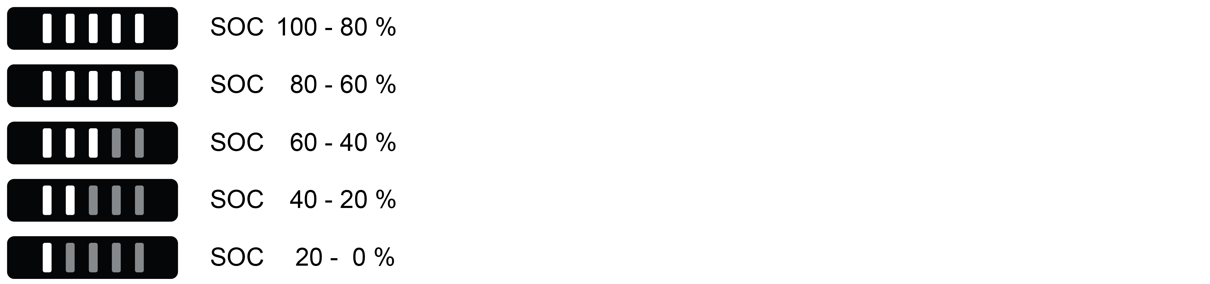
The SoC status display is a visual indication of the system’s current SoC (State of Charge). Each LED represents 20% of the battery capacity.
When discharging, the last bright LED flashes quickly (once a second).
When charging, the last bright LED flashes slowly (once every 2 seconds).
Black Start

Function currently being prepared.
Black Start is a function for powering the inverter up again using energy reserves from the battery if it has been powered down in backup mode, for example.
Pressing the Black Start button makes the energy in the battery available to the inverter in order to start the system. As soon as the inverter starts to run, the Black Start function terminates automatically and the LED goes out.
First Tower

The First Tower function is used to confirm in the system the tower that is connected directly to the inverter.
After commissioning, the First Tower LED lights up (default setting). This means that the tower illuminated as the First Tower is the tower that is connected directly to the inverter.
If several towers are being connected in parallel, First Tower should only be activated for the tower that is connected to the inverter. First Tower should be deactivated for all other towers.
Last Tower

Last Tower is used to confirm the last tower in the system and to terminate the communication connection.
Last Tower is activated as standard upon delivery.
Unlike First Tower, only one tower may be defined as the last tower otherwise the communication loop cannot be fully closed.
Last Tower may only be activated for the last tower.
Therefore, press the Last Tower button on each battery system to check whether the function has been deactivated everywhere other than the last tower (LED off).
If just one tower is being used, First Tower and Last Tower should both be activated for this tower.
Run

If the system is working properly, the Run display will be green.
If the system is not working properly, the Run display will be off. An error has occurred if this happens
and you should check the error messages in the inverter.
Alarm

If the system is working properly, the Alarm display remains off.
In the event of a serious error (including overvoltage, overcurrent, etc.), the Alarm display lights up orange
and you should check the error messages in the inverter.
Module status display

This area indicates the status of up to 9 modules in one single tower. Numbers 1-9 correspond to the modules in the tower, running from top to bottom.
If the module is working properly, the corresponding LED display remains off.
If there is an error in a module, the corresponding number lights up orange
and you should check the error messages in the inverter.