Multi Device Control (MDC) compatibility
The Multi Device Control (MDC) function is available on the PLENTICORE G3 from software version 3.06.10 onwards.
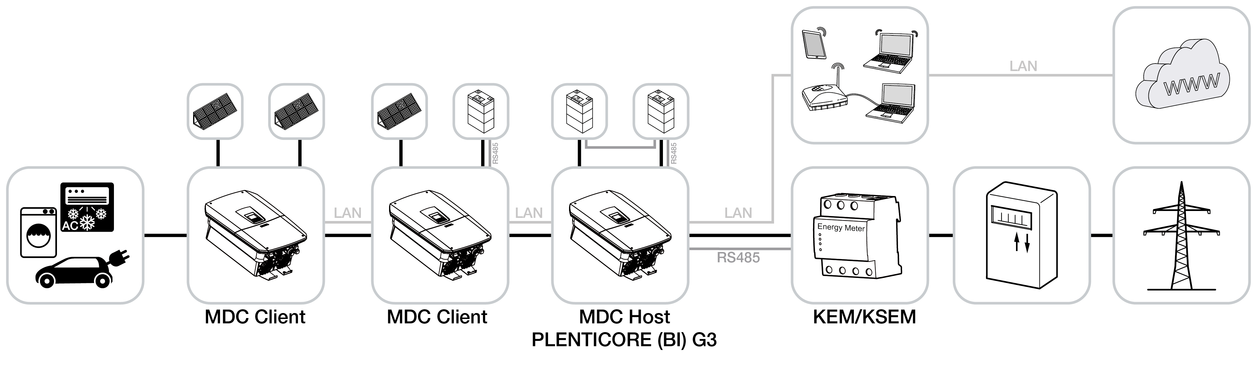
Multi Device Control (MDC) enables the centralised monitoring and control of MDC-compatible inverters and other MDC-compatible devices within the same home network. The control function is handled by a PLENTICORE G3 inverter configured as an MDC host. The MDC host inverter can operate both without a battery and with a battery connected. If a battery is used within the MDC system, it must be connected to the MDC host inverter. If several batteries are used, the battery with the largest usable capacity must be connected to the MDC host.
An MDC system network consists of a maximum of 1 MDC host inverter and 4 MDC client inverters. The clients are controlled by the host.
If several PLENTICORE G3 inverters with batteries have been installed in the domestic grid (max. 3), these are controlled via an MDC host. To do this, the paid product extension / add-on option ‘Battery Control with MDC’ must be activated on the MDC host inverter. If several batteries have been installed in the MDC system network, the battery with the largest capacity must be connected to the MDC host inverter.
Without the ‘Battery Control with MDC’ product extension, only one battery can be connected to and controlled by the MDC host inverter.
It is also possible to control and regulate other MDC client inverters without the product extension if only one battery storage unit is used in the MDC system.
Battery charging strategy for battery control with MDC
If batteries are connected to several inverters (up to a maximum of 3 inverters) and these have the same storage capacity and the same minimum SoC set, they will be charged and discharged evenly.
If the storage capacity and minimum SoC differ, the charging and discharging power is adjusted to the corresponding storage capacity of the battery. In this case, there is a 5% difference in SoC between the host inverter and the client inverters. This means that the MDC host inverter with a battery is always the last inverter to reach 100% SoC and the last to reach the minimum SoC.
Backup mode with battery control using MDC
In backup mode, only the battery connected to the MDC host inverter is used. All other inverters are switched off in backup mode.
For hybrid inverters with a connected battery that have been configured as MDC clients, the connected battery will continue to be charged to 100%.
The following devices and functions are supported by MDC
Below is an overview of the devices that can be controlled via MDC. Please note the current software installed on the G3 inverter.
PLENTICORE G3 with Multi Device Control (MDC)
From software version 3.06.10 onwards, the PLENTICORE G3 can control other G3 inverters, with or without a battery.
The previous method of visualising and controlling multiple inverters via a KOSTAL Smart Energy Meter (KSEM) – which required all inverters to be registered in the KSEM – must not be used with MDC. Simultaneous operation of the control system via both MDC and KSEM is not permitted.
If you have used this option in the past and now wish to switch to visualisation and control via MDC, please check whether any inverters have been added to the KSEM and remove them.
Please note that when using a KOSTAL wallbox, MDC is only compatible with the ENECTOR G2 wallbox (available from Q4/2026) and not with the ENECTOR G1 wallbox.
The same software version must always be installed on all PLENTICORE G3 inverters.
From software version > 3.07.00 onwards, the MDC host ensures that the same software is installed on all PLENTICORE G3 MDC clients. However, for this to work, all MDC inverters in the system network must have previously installed software version 3.07.00.
MDC is constantly being developed, and its range of functions may change. Below is an overview of compatible MDC devices and functions.
The ‘Control via KSEM’ column shows a comparison with the new control option using MDC.
Device type | Control via | Control via |
|---|---|---|
Total number of controllable devices | 5 | 5 |
Total number of controllable devices with a connected battery | 3 | 1 |
PLENTICORE G3 | X | X |
PLENTICORE BI G3 | X | X |
PLENTICORE MP G3 | X | X |
PLENTICORE plus / G2 | - | X |
PLENTICORE BI / G2 | - | X |
PIKO 10 - 20 > FW 5.00 | - | X |
PIKO CI 30/50 G2 | X | X |
PIKO CI 30/50/60 | X | X |
PIKO CI 100 | X | X |
ENECTOR G1 | - | X |
ENECTOR G2 | (from SW 3.7.10) | (from 2.8.0) |
Consumer visualisation via additional KSEM | X | - |
Visualising appliances using Gen2/Gen3 Shelly products (1) | X | - |
Visualisation of consumer data via TQ-Systems energy meters (1) | X | - |
Visualisation of total household consumption | X | X |
Dynamic limitation of the power drawn at the grid connection point | X | ENECTOR (blackout protection) |
Dynamic limitation of feed-in power at the grid connection point | X | X |
Section 9 EEG, Section 14a EnWG with FNN control box | X | - |
Section 9 EEG, Section 14a EnWG with digital interface (EEBus / LPP and LPC) | (from SW 3.7.10) | X |
Dynamic electricity tariffs (for battery charging) | X | - |
INFO

Number of products in the device network
(1) Currently, a maximum of 1 Shelly or TQ-Systems meter can be added to the device network.
If control via MDC is not possible in your system network because no compatible devices have been installed, control must be carried out via a KOSTAL Smart Energy Meter (KSEM). Please refer to the document ‘Connecting multiple inverters’, which you can find in the product’s download section.