Communication settings
Set the inverter's network communication parameters. (e.g. Ethernet (LAN)/WLAN/WiFi/RS485 settings).
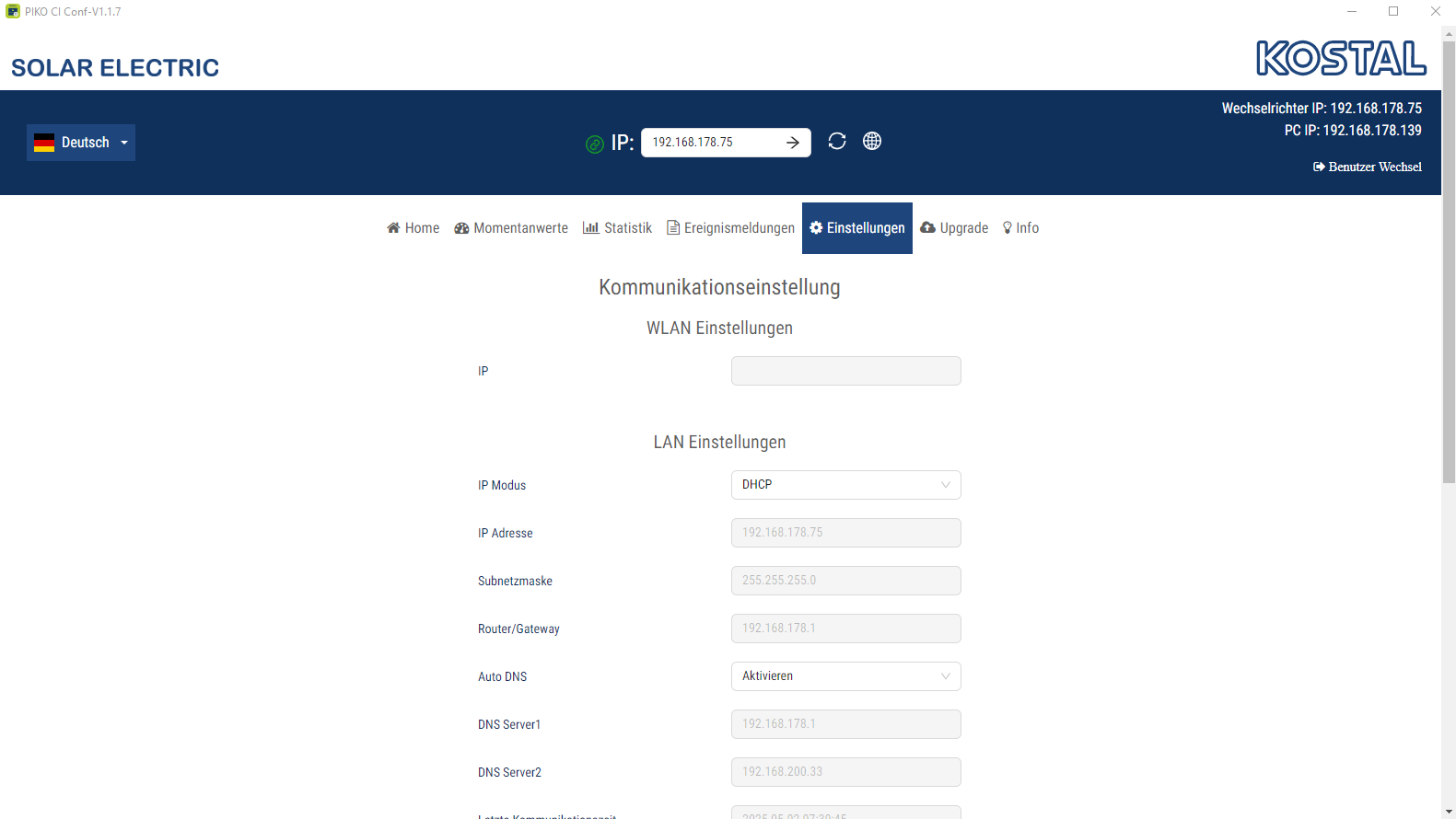
WLAN settings
WLAN settings | Explanation |
|---|---|
IP | WLAN IP address of the inverter WiFi module. |
LAN settings
Parameter | Explanation |
|---|---|
IP mode | The DHCP option is activated by default. This means that the inverter obtains its IP address from a DHCP server. Select static IP to assign the IP address yourself in IP address. It goes without saying that this address must be available in your system. |
IP address | Enter IP address of inverter. If the inverter is not allocated an IP address automatically through a DHCP server, the inverter can be configured manually. The data necessary for configuration, such as IP, subnet mask, router and DNS addresses, can be found on your router/gateway. |
Subnet mask | Enter the subnet mask e.g. 255.255.255.0 |
Router/gateway | Enter the IP address of the router/gateway |
Auto DNS | The Auto DNS option is activated by default. This means that inverters can also be addressed using a name instead of an IP address. For this purpose, the IP addresses of the DNS servers must be entered. |
DNS server 1 | Enter the IP address of the DNS server (Domain Name System) |
DNS server 2 | Enter the IP address of the backup DNS server (Domain Name System) |
Last time of communication | Shows when communication with the inverter last took place. |
Launch network diagnostics | Starts network diagnostics. The result is subsequently shown. |
Communication status | Shows the status of communication with the grid. |
RS485 settings
Parameter | Explanation |
|---|---|
Baud rate | RS485 transmission rate |
Data bit | RS485 data bit |
Stop bit | RS485 stop bit |
Parity bit | RS485 parity bit |
Terminating resistor | Activate terminating resistor for the RS485 bus. This must be activated on the last inverter connected to the RS485 bus. |
Modbus address | Modbus address |