Manual inverter planning
With manual planning, you select the inverter yourself and can connect it with the PV modules that have already been planned.
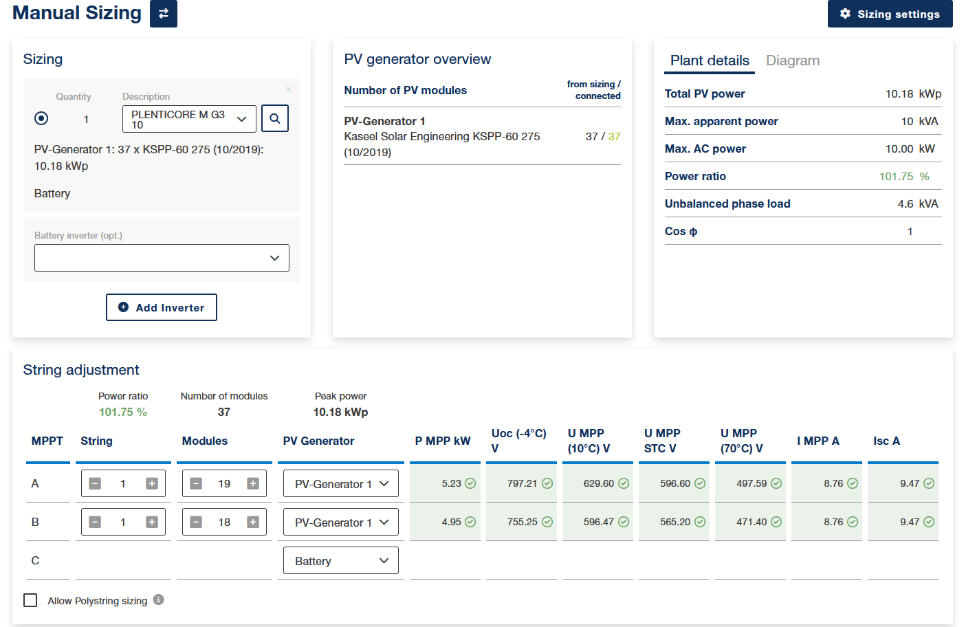
You can select the inverter from a database to use in the connection.
- Firstly, go to Select inverter to select an inverter. You can also narrow down the selection further by using filters.
- Connect the inverter with the PV modules that have already been planned. If a connection is outside of the inverter specifications, a notice, warning or error will be displayed.
- Connect the battery to a hybrid inverter or alternatively select a battery inverter. Note: The battery can be connected to either the hybrid inverter or the battery inverter.
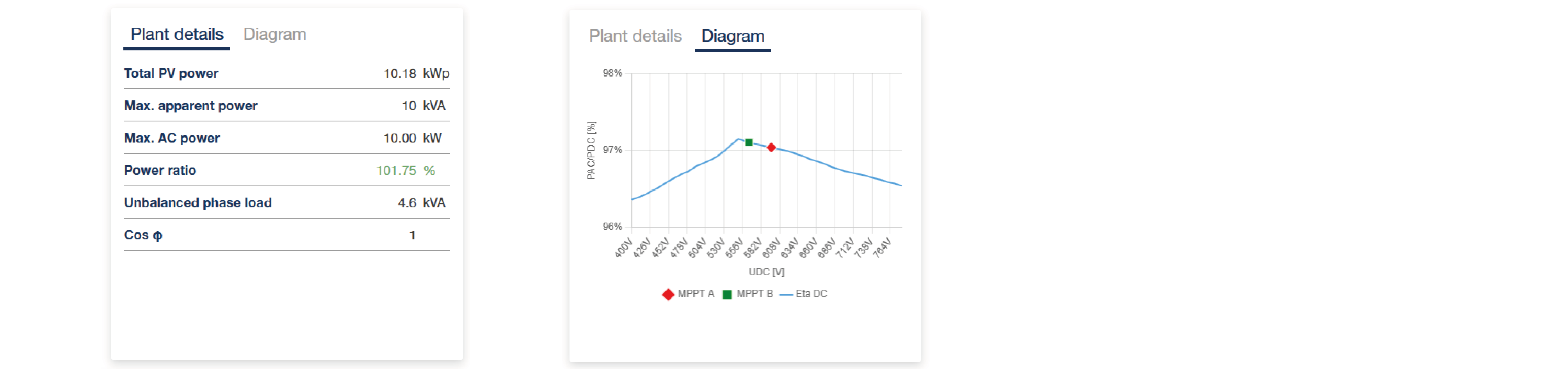
Switching view
You can switch the view between system details and the MPPT diagram.
Polystring
When connecting the inverter, you can factor in a polystring connection. Using the polystring connection, different PV generators with the same PV module type can be connected to the same MPP tracker. The number of modules for the PV module type in the strings must be identical.
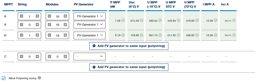
If you want to delete the polystrings again, untick the checkbox.
INFO

If you have completed visual planning, the exact number of PV modules must be taken into account in the manual connection.
Sizing settings for inverters/PV generators
You can set several parameters for inverters and PV generators by going to the sizing settings. This more accurately restricts the sizing. Alternatively, you can use the standard settings.
Specify the following values here and save them:
Device | Parameters |
|
|---|---|---|
Inverter | Power ratio min./max. | Usually, inverters are sized smaller than the total generator power. Adopt the standard value or enter your own value here (20–200, standard values min. 80/max. 120). |
Cos phi (type) / (value) | Specify the type and value for cos phi. | |
Limitation of the active power to [%] | Specify the active power that the inverter should be limited to when feeding into the public grid, e.g. 70%. The value is usually prescribed by the energy provider. | |
Maximum unbalanced phase load [kVA] | Specify the maximum unbalanced phase load. In Germany, this is 4.6 kW, for example. (0–6, standard value 4.6) | |
PV generator | Min./max. module temperature [°C] | Enter here the minimum and maximum module temperature (-50 – 200, standard value -10 / 70) |
Module temperature Uoc [°C] | Enter here the module temperature at idling voltage (-50 – 200, standard value 25) | |
Isc factor | If the Isc factor should be taken into consideration, select this in the settings and enter a current safety factor. Using the value, you can take a current safety factor into consideration in the sizing. |