PIKO MP plus - load/generation measurement
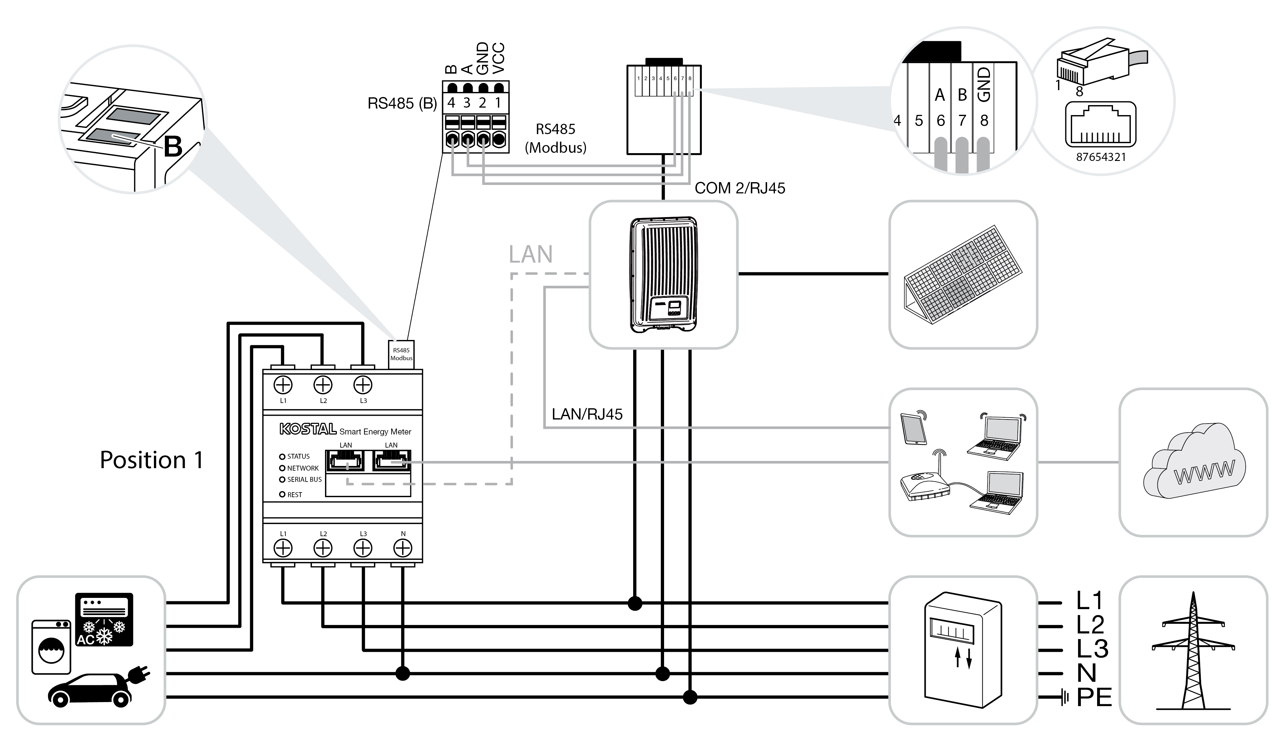
Installation position – home consumption (position 1)
The installation position cannot be used for a PIKO MP plus with battery or in a multiple-inverter connection.

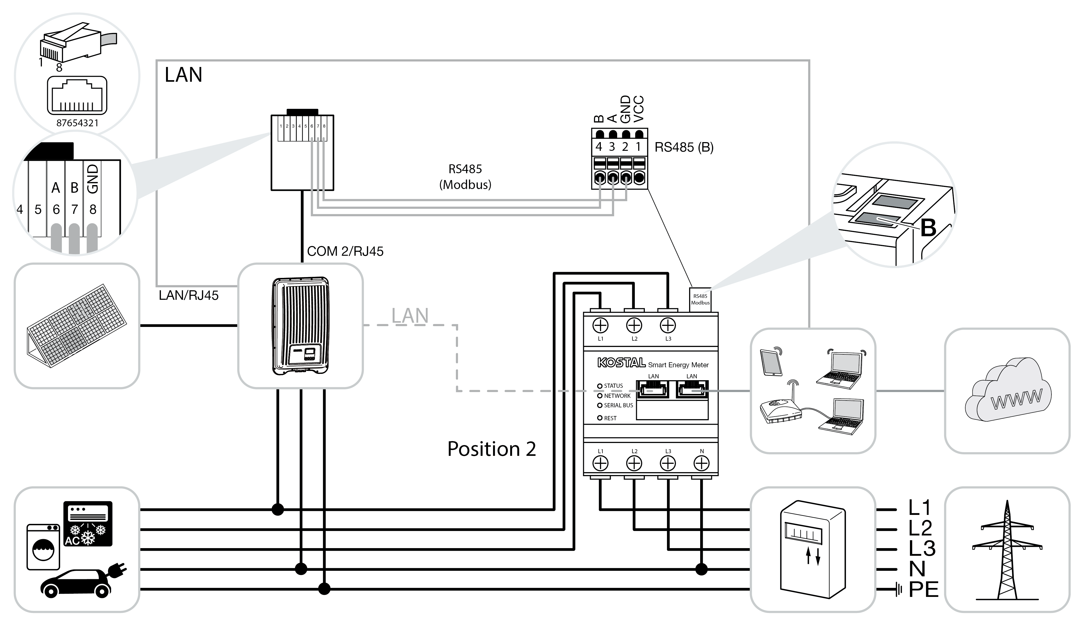
Installation position – grid connection point (position 2 – standard)

Install the KOSTAL Smart Energy Meter in the house grid as shown.
INFO

The installation position of the KOSTAL Smart Energy Meter is set in the inverter.
Set up RS485 communication cable between inverter and KOSTAL Smart Energy Meter and connect.
Establish LAN connection from KOSTAL Smart Energy Meter and inverter to the Internet. As an option, the LAN connection from the inverter can also be connected directly to the KOSTAL Smart Energy Meter (switch function).
INFO

When an inverter is selected, the predefined default values are adopted. These can be adapted if necessary.
INFO

For details, see the inverter's operating manual and the KOSTAL Smart Energy Meter's installation instructions.
In this variant, the KOSTAL Smart Energy Meter runs as a slave and transmits data to the inverter.
The inverter does not have to be set up in the KOSTAL Smart Energy Meter because it is pre-configured to the Modbus RTU RS485 interface (B) as standard.
If changes are to be made to the settings, perform the following steps:
- Call up online interface of KOSTAL Smart Energy Meter Calling up user interface
- Call up Modbus configuration under Modbus settings.
- Select the PIKO MP plus from drop-down list

Press the Savebutton to adopt the settings.
INFO

When an inverter is selected, the predefined default values are adopted. These can be adapted if necessary.
Parameter | Value |
|---|---|
Interface | RS485 B |
Mode | Slave |
Presetting | PIKO MP plus |
Slave address | 247 |
Baud rate | 19200 |
Data bits | 8 |
Parity | Even |
Stop bit | 1 |