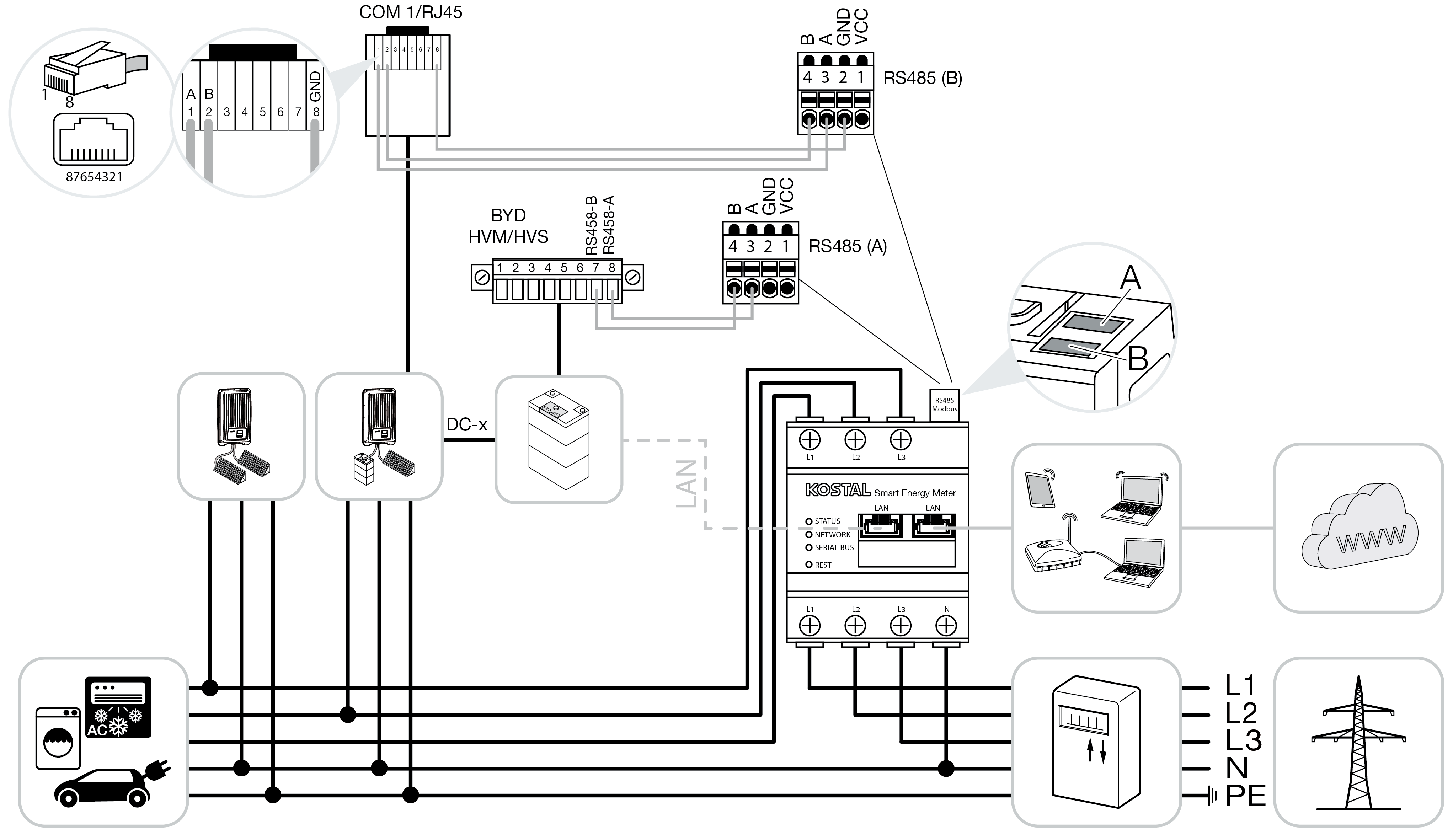
PIKO MP plus - battery control

Install the KOSTAL Smart Energy Meter at the grid connection point in the house grid as shown.
INFO

The installation position of the KOSTAL Smart Energy Meter can no longer be set in the PIKO MP plus when battery management is activated in the KOSTAL Smart Energy Meter. It is absolutely essential that the KOSTAL Smart Energy Meter is fitted at the grid connection point.
Set up RS485 communication cable between inverter and KOSTAL Smart Energy Meter RS485 (B) and connect.
Set up RS485 communication cable between battery and KOSTAL Smart Energy Meter RS485 (A) and connect.
Establish LAN connection from KOSTAL Smart Energy Meter, battery and inverter to the Internet. As an option, the LAN connection from the inverter or battery can also be connected directly to the KOSTAL Smart Energy Meter (switch function).
INFO

For details, see the inverter's operating manual and the KOSTAL Smart Energy Meter's installation instructions.
In this variant, the KOSTAL Smart Energy Meter runs as a master and transmits data to the inverter and battery.
- When setting up, note the following installation order:
INFO

The battery must be assigned to a DC input in the PIKO MP plus. This is done in the PIKO MP plus by going to Settings > Service > Inputs > DCx > Battery.
- Switch off inverter by pressing DC switch
- Switch off battery using main switch
- Switch on battery using main switch
- Set up inverter and battery in KOSTAL Smart Energy Meter
- Switch on inverter by pressing DC switch
INFO

Nature and source of hazard
If the battery is switched off manually for any reason, observe the following order for switching on:
- Switch off inverter
- Switch on battery
- Switch on inverter
The PIKO MP plus and battery must be set up in the KOSTAL Smart Energy Meter.
Do this by performing the following steps:
- Call up online interface of KOSTAL Smart Energy Meter Calling up user interface
- For a battery to be used with the PIKO MP plus, the function for this must be released in the KOSTAL Smart Energy Meter. To do this, activate the battery management under Activation code .
INFO

Input of an activation code, e.g. to connect a battery. This first has to be purchased from the KOSTAL Solar online shop.
- Then you can set up the devices. To do this, go to Inverter > Devices (manage the inverters used).
- Use the plus symbol to add an inverter.
INFO

When an inverter is selected, the predefined default values are adopted. These can be adapted if necessary.
Parameter | Value |
|---|---|
Series | Select PIKO MP plus. |
Type | Select the appropriate type/power class of the inverter. This automatically sets the inverter's maximum AC output power. |
Serial interface | Select the RS485 interface at which the PIKO MP plus is connected to the KOSTAL Smart Energy Meter. |
Timeout | Accept default value. |
Maximum output power | It is essential that this value is set for every connected inverter. By selecting the type/inverter power class, the inverter's maximum output power is automatically set. The maximum output power is the maximum output which the inverter being configured is able to deliver. |
Battery management | Activate battery support. |
Serial interface for battery | Specify the RS485 interface of the KOSTAL Smart Energy Meter to which the communication line of the battery has been connected. |
Battery type | Select the battery type, e.g. BYD HVM or BYD HVS. |
Number of modules | Select the number of modules that are installed in the battery. |
Max. SOC (charging status) | Set the battery's maximum charging status (default 100%). |
Min. SOC (charging status) | Set the minimum charging status of the battery. Note the details provided by the battery manufacturer (default 5%). |
Nominal charging/final charging capacity of battery | This value is set automatically and does not need to be changed. It is calculated by the battery type and the number of modules. However, it can be adjusted if the values do not match the battery. |
Open advanced settings | |
RS485 address | Enter the inverter’s RS485 address. This must be unique for each device and must not already exist. |
- Press the Save button to adopt the settings.
- The PIKO MP plus and battery have been set up in the KOSTAL Smart Energy Meter.