Replacing AC / DC overvoltage protection modules
Type 2 DC and AC overvoltage protection modules are fitted in the inverter to protect against overvoltage. In the event of a fault, these can be replaced. An event message is output on the inverter for this purpose.
We recommend always replacing all overvoltage protection modules on the DC or AC side rather than just the faulty ones. Usually the modules that are not faulty are also damaged by the overvoltage damage.
The following module types are used:
Page | Quantity | Type |
|---|---|---|
DC | 13 | PV DC SPD - Type 2 / PV 670-25M2-10R |
AC | 3 | PV DC SPD - Type 2 / PV 500-25M2-10R |
2 | PV DC SPD - Type 2 / PV 670-25M2-10R |
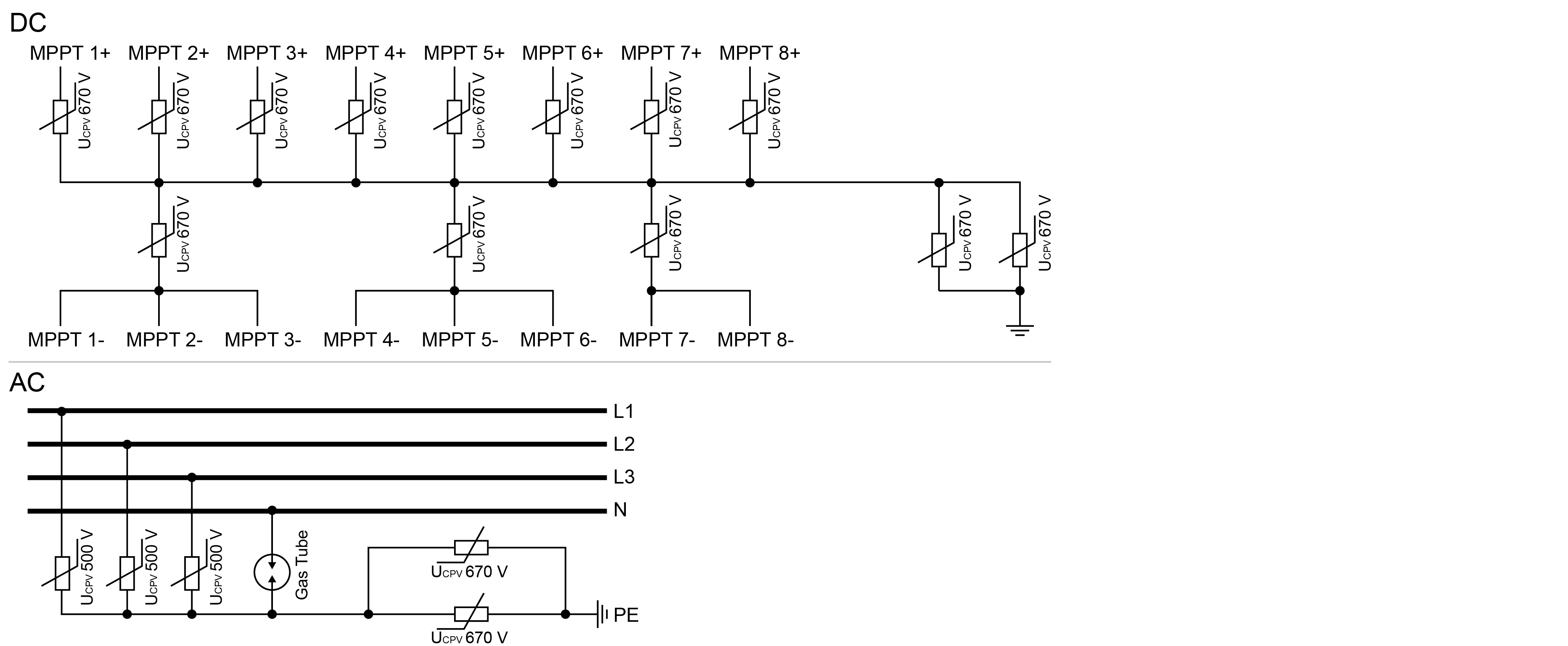
Block diagram for AC / DC overvoltage modules
Replacing overvoltage protection modules
DANGER
Risk of death due to electrical shock and discharge!
De-energise device and secure against being switched on again.
INFO

Whenever working on the inverter, only ever use insulated tools to prevent short-circuits.
- Disconnect the power supply from the mains.
- Secure AC connection against being switched on again.
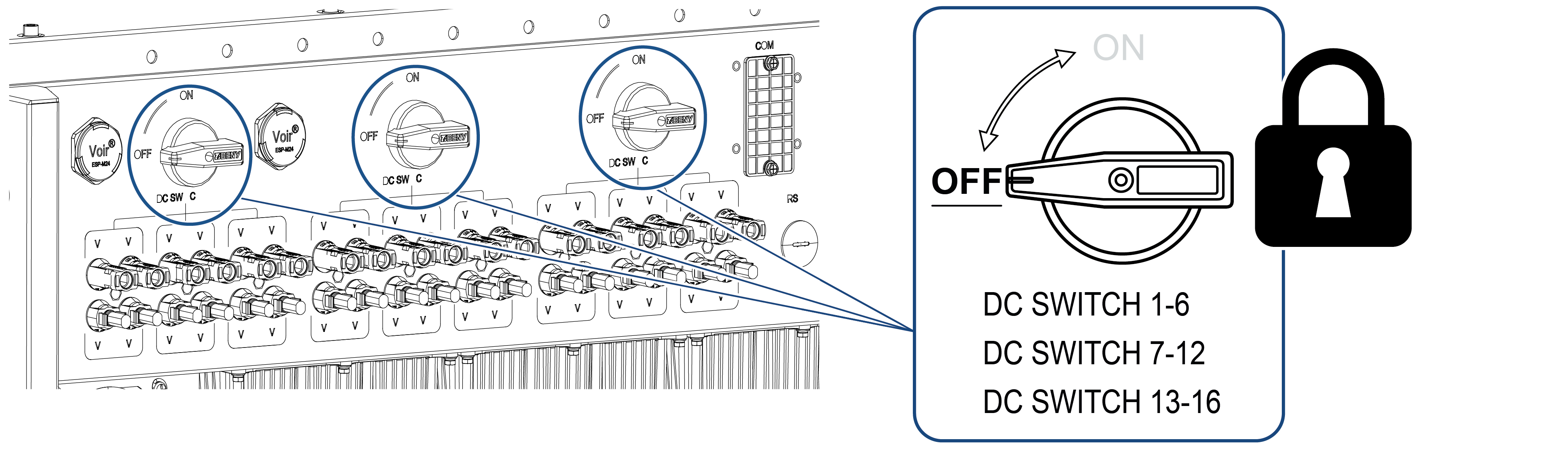
- Switch the DC switch on the inverter to OFF.
- Wait at least 10 minutes after disconnecting the unit until the internal capacitors have discharged.
- Remove the inverter's cover and open the inverter.
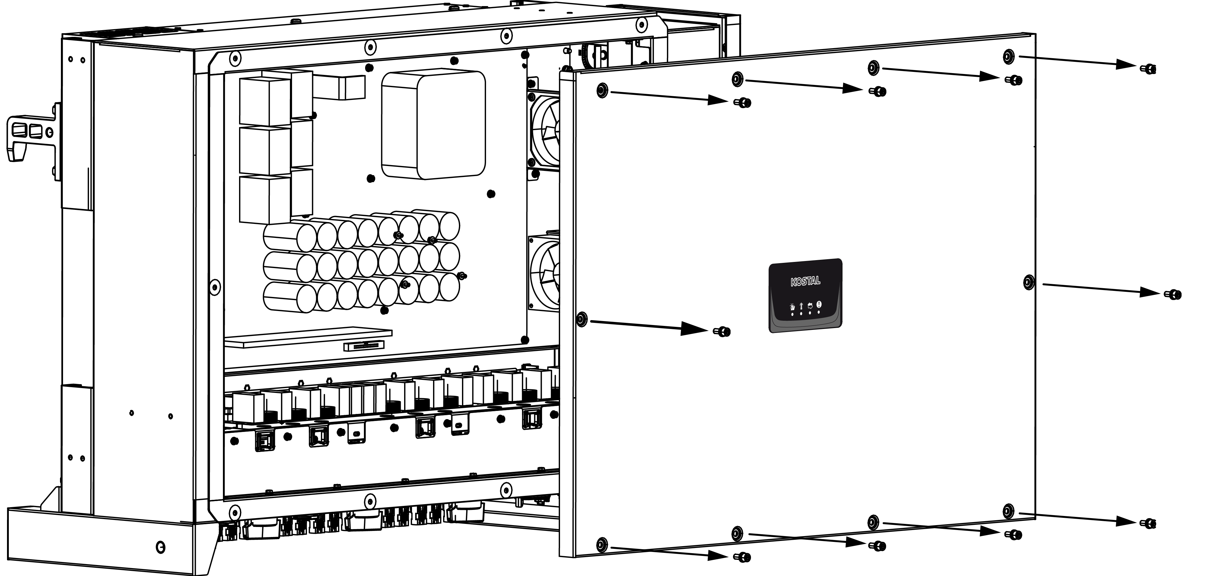
- Remove defective overvoltage protection modules and replace with new ones.
Defective modules can be recognised by a red mark in the module housing. 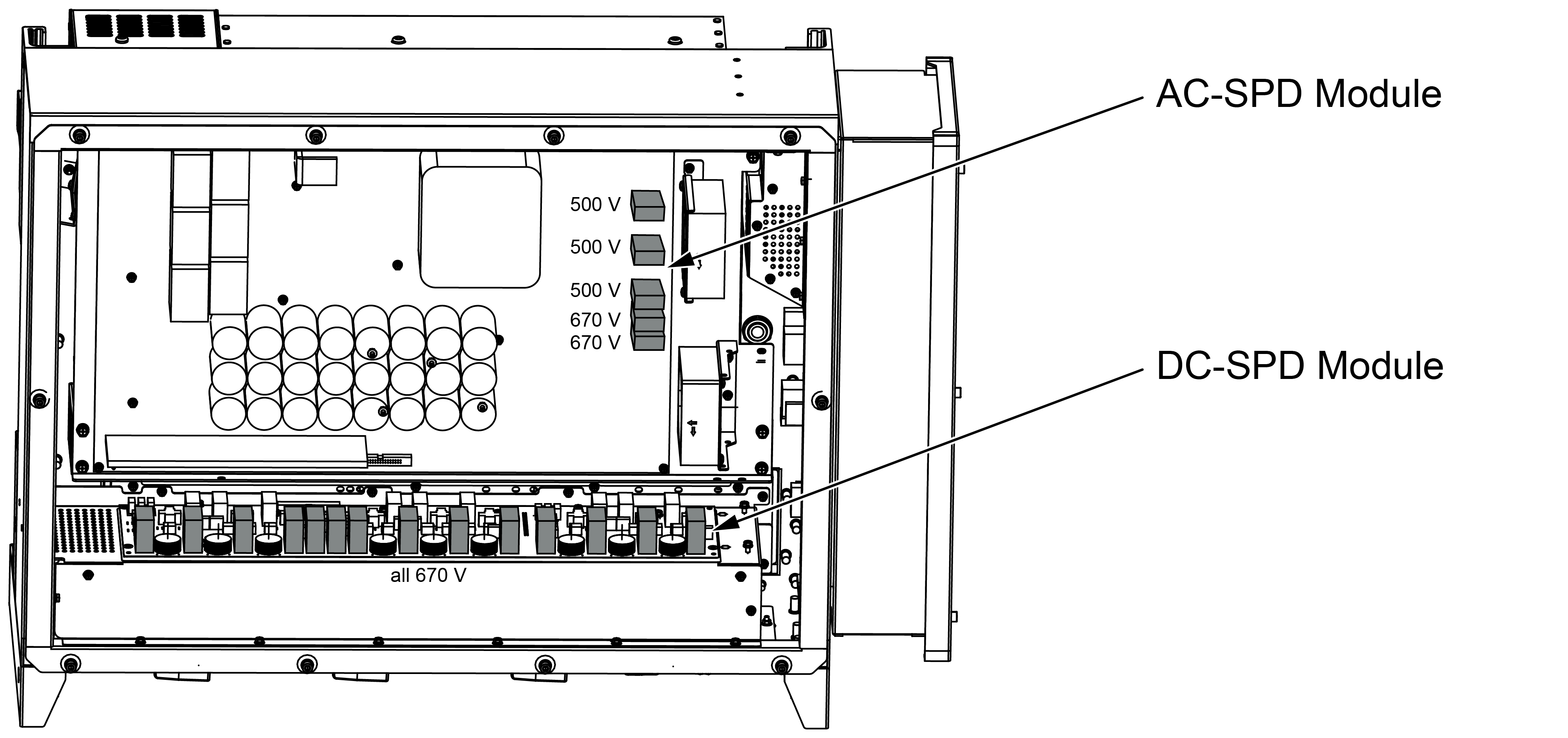
- Install cover and screw it tight (3 Nm).
- Switch on the inverter again.
- The PV fuses have been replaced.