Overview of communication connections
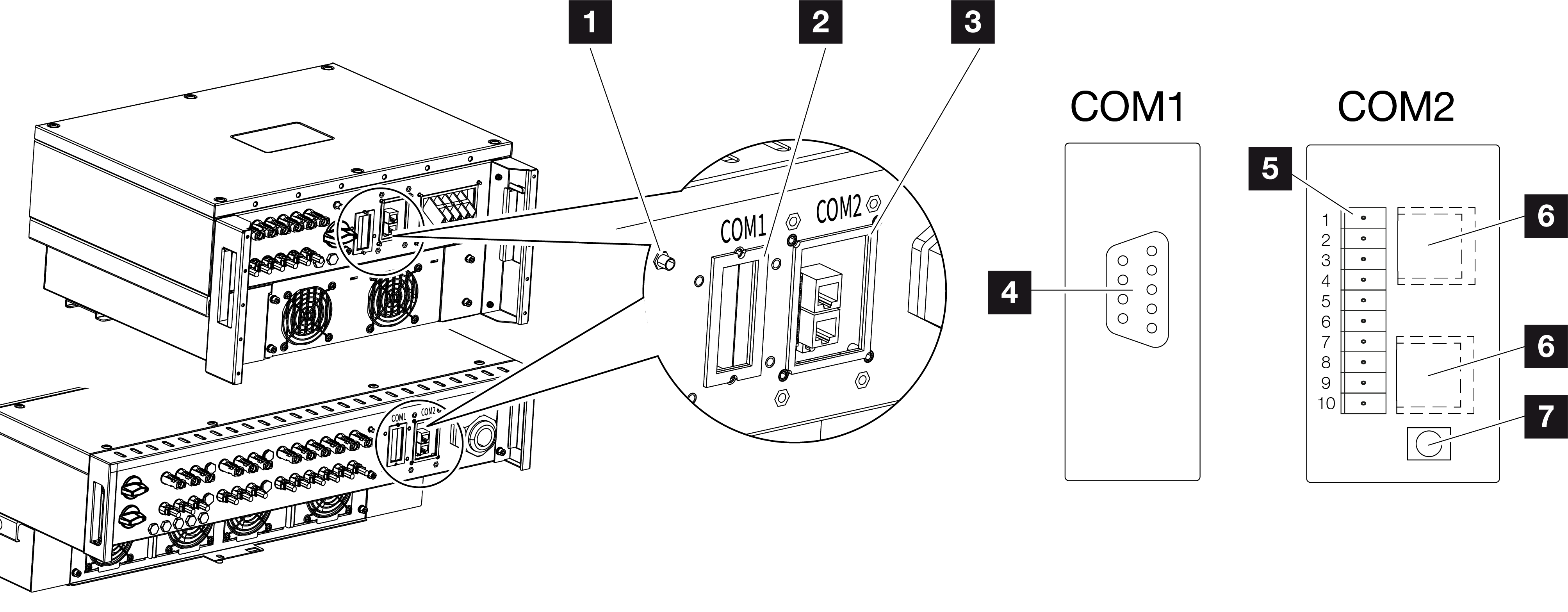
1 | WiFi antenna |
2 | COM1 connection panel |
3 | COM2 connection panel |
4 | Socket for communication module |
5 | Connector strip for communication interface with RS485 interface, digital inputs for ripple control receiver and grid and system protection connection |
6 | LAN connection |
7 | Reset button for commissioning address (WLAN) |
Item | Designation | Pin | Explanation |
|---|---|---|---|
5 | Communication interface | 1 | GND (ground) for Remote and DI1…4 |
2 | Remote: Central system protection | ||
3 | DI4: Input 4 | ||
4 | DI3: Input 3 | ||
5 | DI2: Input 2 | ||
6 | DI1: Input 1 | ||
7 | RS485/Modbus interface B (input, data –) | ||
8 | RS485/Modbus interface A (input, data +) | ||
9 | RS485/Modbus interface B (output, data –) | ||
10 | RS485/Modbus interface A (output, data +) | ||
6 | RJ45 terminal | – | LAN connection 1 |
– | LAN connection 2 |