Communication connection for KOSTAL Smart Energy Meter via LAN
Wiring diagram for energy meter LAN - grid connection
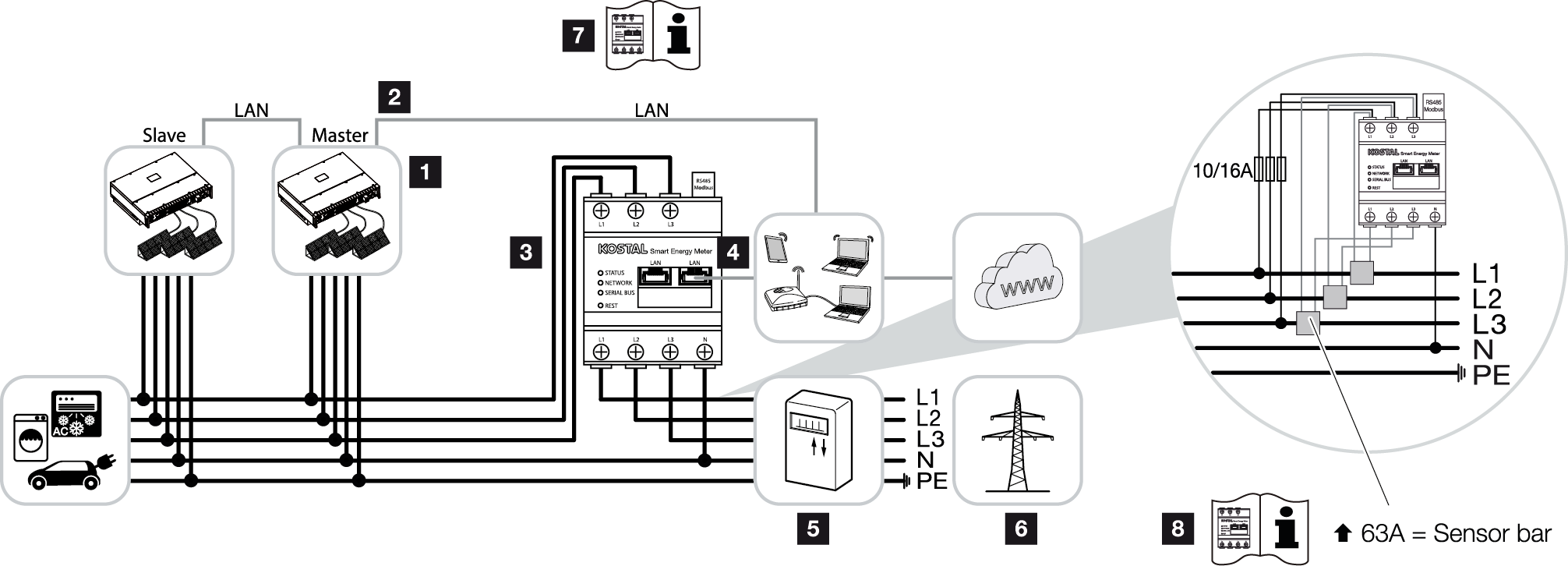
1 | Inverter |
2 | LAN interface for inverter |
3 | KOSTAL Smart Energy Meter |
4 | LAN interface for KOSTAL Smart Energy Meter |
5 | Feed meter |
6 | Public grid |
7 | Read the operating manual of the KOSTAL Smart Energy Meter. |
8 | Use a current transformer for currents above 63 A. Read the operating manual of the KOSTAL Smart Energy Meter. |
Connecting the KOSTAL Smart Energy Meter
DANGER
Risk of death due to electrical shock and discharge!
De-energise all devices and secure them against being switched on again.
INFO

Use an Ethernet cable of category 7 (Cat 7, FTP) with a maximum length of 100 m as a network cable (Ethernet 10BaseT, 10/100 MBit/s).
- De-energise the mains cable.
- Install the KOSTAL Smart Energy Meter as shown in the illustrations at the grid connection point in the house grid.
- Feed the Ethernet cable on the inverter through the COM2 cover and seal it with sealing ring and union nut. Tighten union nut to the prescribed torque.
Tightening torque: 8 Nm (M25). 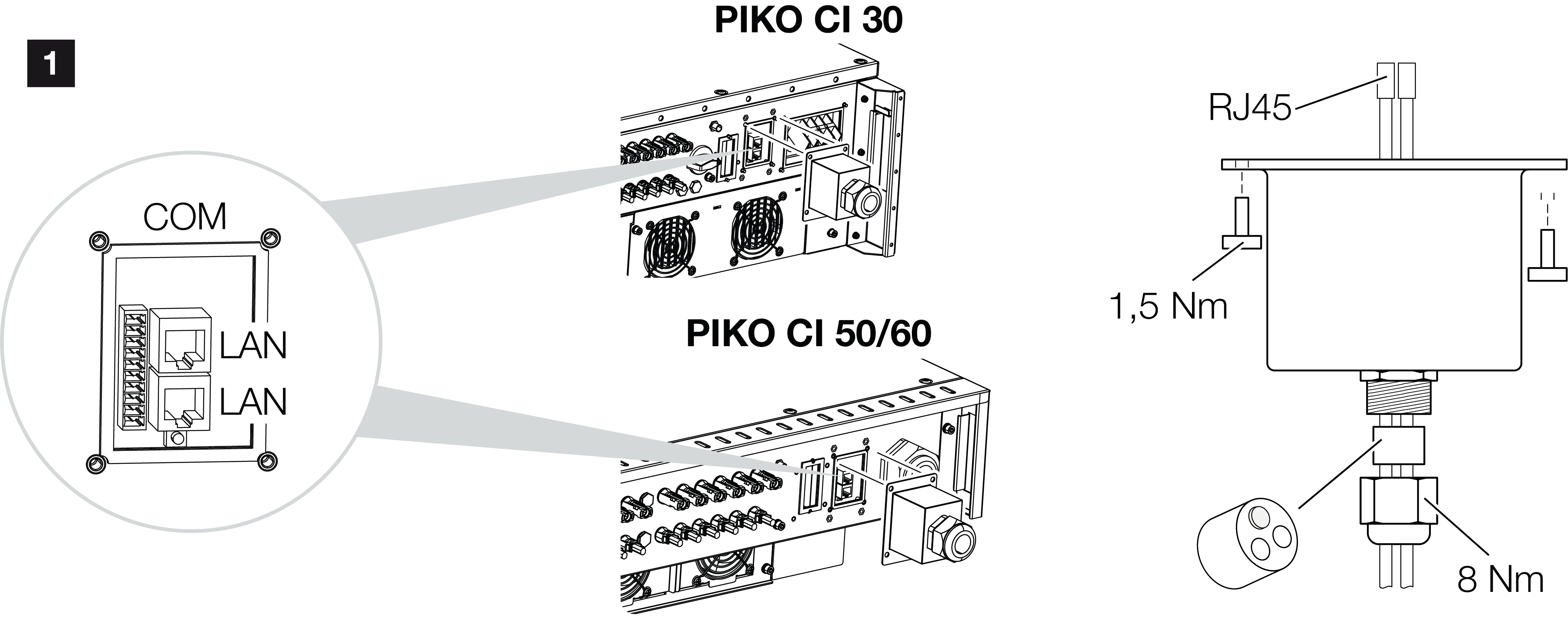
- Connect Ethernet cable to one of the LAN sockets in the COM2 connection panel. The second LAN socket is used to continue the network connection to further inverters.
- Mount COM2 cover cap.
Torque: 1.5 Nm - Connect the other end of the Ethernet cable to the router.
- Establish a LAN connection from the KOSTAL Smart Energy Meter to the router.
- Inverter connected to KSEM.
After commissioning
After commissioning, the following settings still have to be configured in the KOSTAL PIKO CI Conf App.
Configuring settings using the KOSTAL Smart Energy Meter user interface
- In the KOSTAL Smart Energy Meter, set Modbus settings > Modbus TCP > Slave (Enable TCP Slave) to ON.
- To make the home consumption visible in the KOSTAL Solar Portal, in the KOSTAL Smart Energy Meter set Inverter > Solar portal > Activate solar portal to ON.
In this variant, the KOSTAL Smart Energy Meter works as a slave and sends data to the inverter.
Configuring settings using the KOSTAL PIKO CI App
- Use of the KOSTAL Smart Energy Meter (KSEM) must be configured in the KOSTAL PIKO CI Conf App on the master inverter.
For this purpose, go to Settings > Inverter settings > Power adaptation/control > KSEM management > Activate/deactivate KSEM > Activate. - The connection between KSEM and inverter is set by going to Settings > Inverter settings > Power adaptation/control > KSEM management > Connection between KSEM and master inverter > LAN.
- The installation position is set by going to Settings > Inverter settings > Power adaptation/control > KSEM management > Sensor position > Grid connection point.
- The KSEM modbus address is set by going to Settings > Inverter settings > Power adaptation/control > KSEM management > Energy meter modbus address > 1 (standard value in KSEM).
- A power limitation of the grid feed-in (e.g. to 70%) must be entered in watts on the Master inverter.
The active power limitation is entered by going to Settings > Inverter settings > Power adaptation/control > KSEM management > Limitation of the active power to (W). - The KSEM IP address is entered at Settings > Inverter settings > Power adaptation/control > KSEM management > Energy meter IP address > KSEM IP address.
- All other inverters connected to the master inverter are configured as slaves. Do not configure any further settings in slave inverters.
- Inverters configured.