Block diagrams
Block diagram for PIKO CI 30
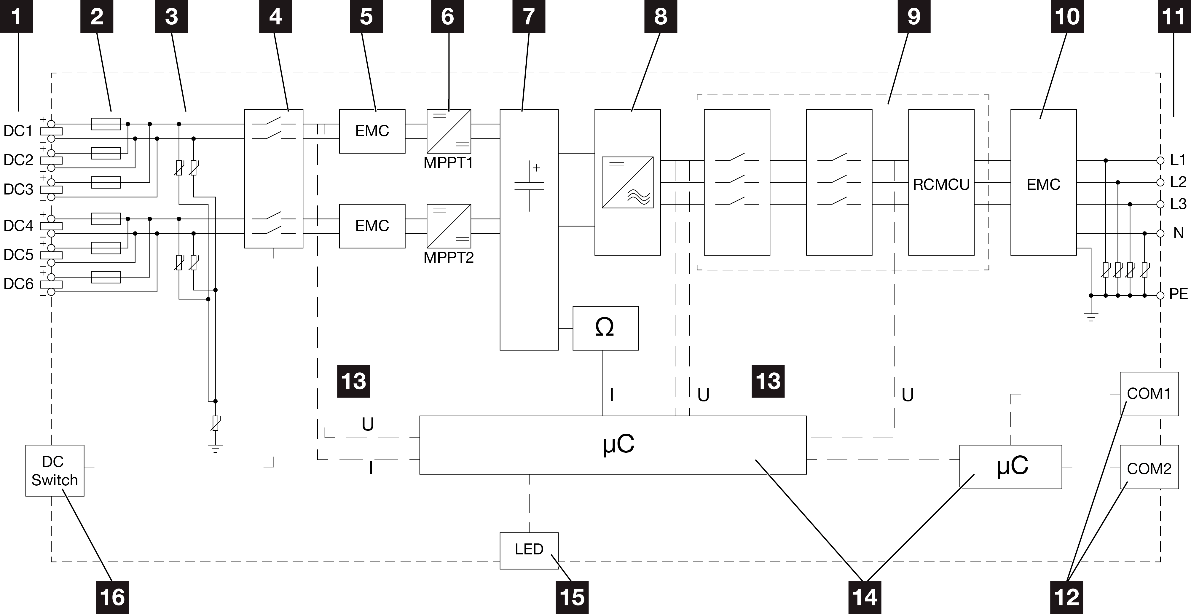
1 | DC inputs for PV modules |
2 | DC fuses |
3 | Integrated overvoltage protection (DC side) |
4 | Electronic DC disconnection device |
5 | EMC filter (DC side) |
6 | DC regulator |
7 | Intermediate circuit |
8 | Inverter bridge circuit |
9 | Grid monitoring and shutdown |
10 | EMC filter (AC side) |
11 | AC connection |
12 | COM1 and COM2 connection panels for communication interfaces |
13 | Voltage and current measurement |
14 | Control system and communication |
15 | Status LED |
16 | DC switch |
Block diagram for PIKO CI 50
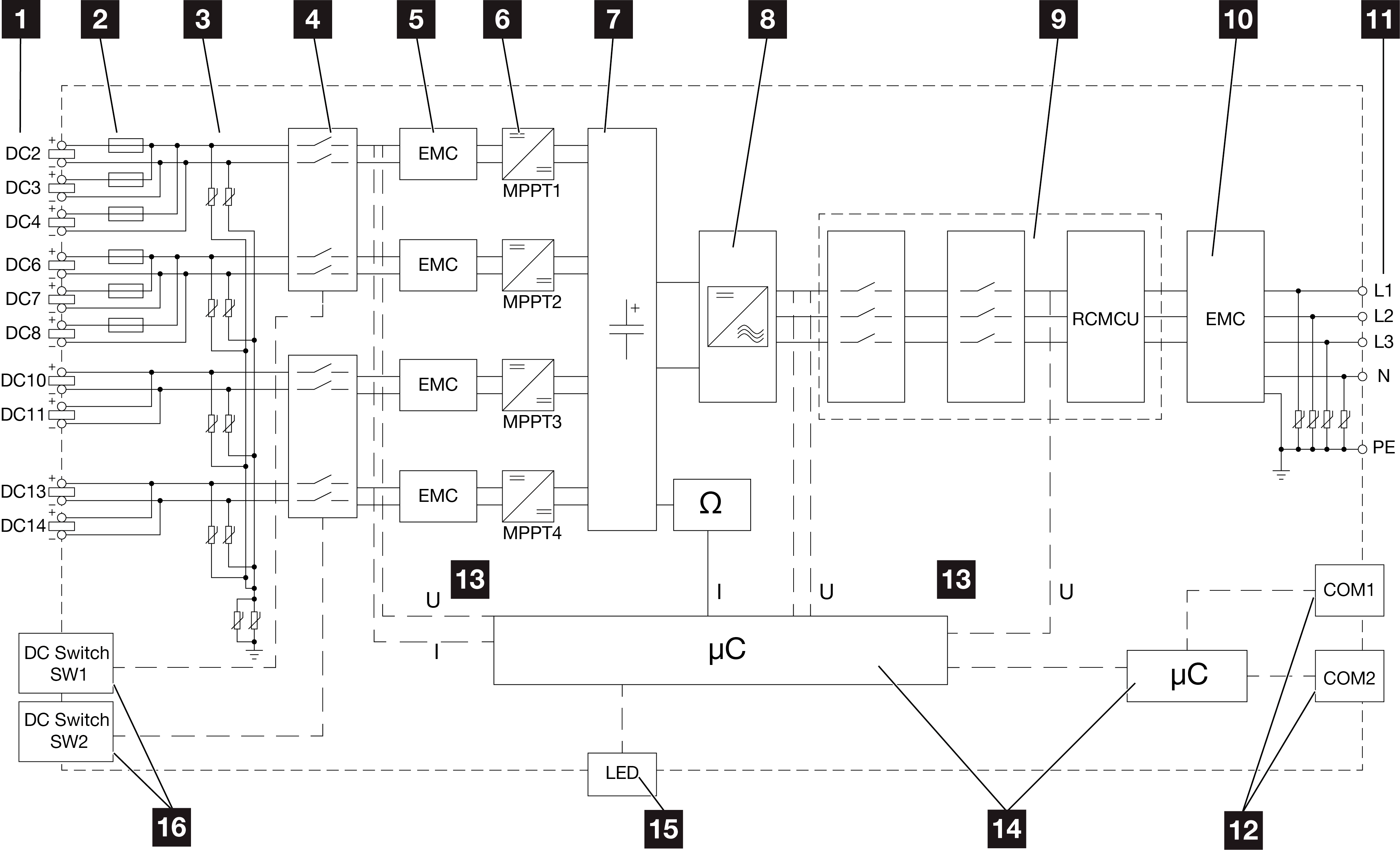
1 | DC inputs for PV modules |
2 | DC fuses |
3 | Integrated overvoltage protection (DC side) |
4 | Electronic DC disconnection device |
5 | EMC filter (DC side) |
6 | DC regulator |
7 | Intermediate circuit |
8 | Inverter bridge circuit |
9 | Grid monitoring and shutdown |
10 | EMC filter (AC side) |
11 | AC connection |
12 | COM1 and COM2 connection panels for communication interfaces |
13 | Voltage and current measurement |
14 | Control system and communication |
15 | Status LED |
16 | DC switch |
Block diagram for PIKO CI 60
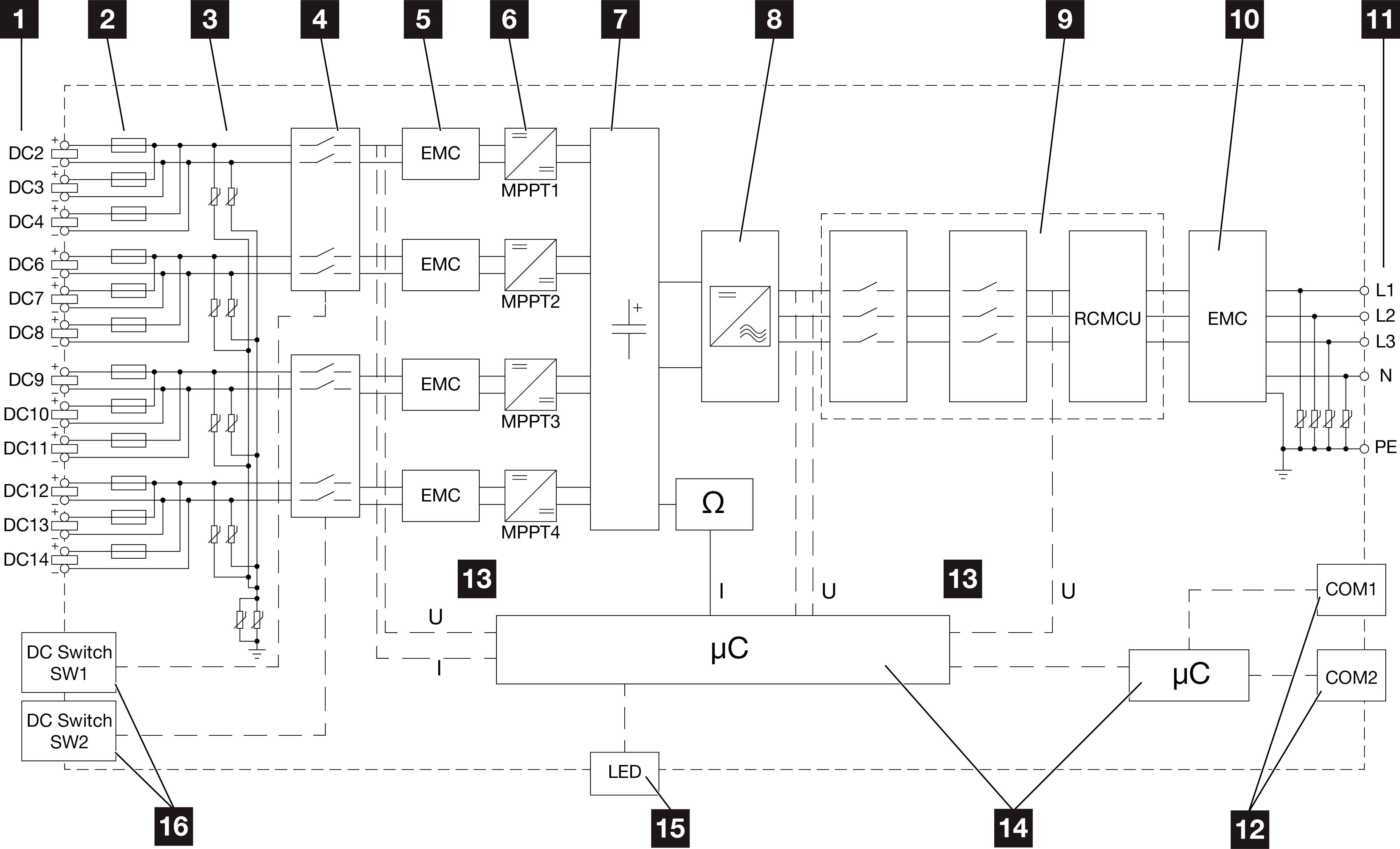
1 | DC inputs for PV modules |
2 | DC fuses |
3 | Integrated overvoltage protection (DC side) |
4 | Electronic DC disconnection device |
5 | EMC filter (DC side) |
6 | DC regulator |
7 | Intermediate circuit |
8 | Inverter bridge circuit |
9 | Grid monitoring and shutdown |
10 | EMC filter (AC side) |
11 | AC connection |
12 | COM1 and COM2 connection panels for communication interfaces |
13 | Voltage and current measurement |
14 | Control system and communication |
15 | Status LED |
16 | DC switch |