Communication via RS485
Connecting inverter with RS485 cable
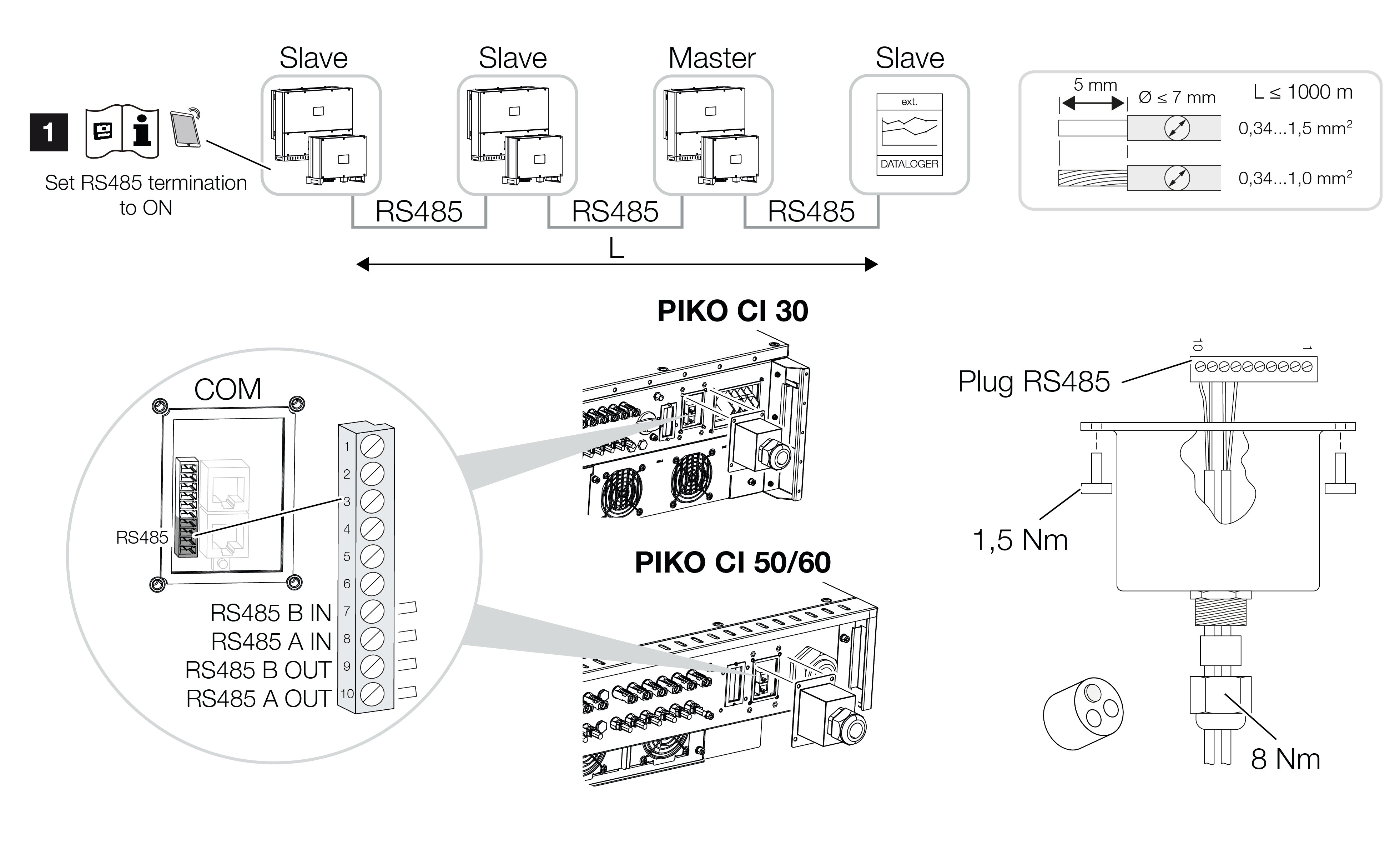
1 | Activate RS485 termination on the last inverter. |
Connecting the RS485 connection
- De-energise the inverter. Switching off the inverter
- Lead the RS485 cable through the COM2 cover and seal it with sealing ring and union nut.
- Tighten union nut to the prescribed torque.
Torque: 8 Nm (M25). INFO

Requirements of communication cable:
Wire cross-section from 0.34 to 1.5 mm² (rigid) or 0.34 to 1.0 mm² (flexible)
Bus length max. 1000
Length of stripped insulation approx. 5 mm
- Fit RS485 cable to the supplied plug (RS485 x in) and plug it into the interface in the COM2 connection panel. RS485 out is used to continue the network connection to further inverters.
- Connect RS485 cable to external device (e.g. data logger).
INFO
After commissioning, the settings for the RS485 connection still have to be configured in the app.
This includes, for example, setting the transmission speed.
- The inverter is set as Master LAN or slave using the KOSTAL PIKO CI app on each inverter. To do this, go to Settings > Communication settings > Master/Slave settings > Master/Slave settings and then select Master LAN or Slave. The master forwards data to the slave inverters. This can be, for example, a feed-in limitation.
- The RS485 termination of the last inverter must be set to ON in the app. This can be done under Settings > Communication settings > RS485 Settings > Terminating resistor.
- RS485 cable connected.