Connecting ripple control receiver
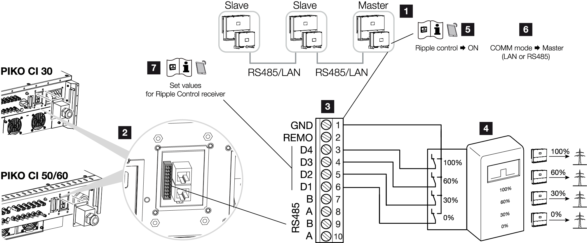
1 | Inverter to which the ripple control receiver is connected |
2 | COM2 connection panel |
3 | Plug for communication interface |
4 | Ripple control receiver |
5 | Activate ripple control receiver in the KOSTAL PIKO CI app |
6 | Activate communication mode (LAN or RS485) in the KOSTAL PIKO CI app |
7 | Activate switching values for ripple control receivers in the KOSTAL PIKO CI app |
Several energy supply companies offer the owners of PV systems the possibility of regulating their system with variable active power control and thus increasing the feed-in into the public grid to up to 100%.
INFO

In some applications, the digital KOSTAL Smart Energy Meter may be regarded as a cost-effective alternative to the ripple control receiver. Here the feed-in may well be limited by the energy supply company, but the inverter controls the flow of energy (self-consumption in house grid and feed-in to the public grid) in such a way that the self-produced energy is not lost or loss is kept to an absolute minimum.
Ask your energy supply company or installer what application rule applies to you or whether there is an alternative (e.g. smart meter) better suited to you.
If a ripple control receiver is already connected to another KOSTAL inverter in your home network, you can use the control signals of this ripple control receiver.
- De-energise the mains cable.
DANGER
Risk of death due to electrical shock and discharge!
De-energise all devices and secure them against being switched on again.
- Fit ripple control receiver in control cabinet or power distributor.
- Correctly route the communication cable from the inverter to the control cabinet and connect following wiring diagram provided by manufacturer.
INFO
Requirements of communication cable:
- Wire cross-section from 0.34 to 1.5 mm² (rigid) or 0.34 to 1.0 mm² (flexible)
- Length max. 30
- Length of stripped insulation approx. 5 mm
- Pass the communication cable through the cover for the COM2 connection panel. Seal connection with sealing ring and union nut.
- Connect the communication cable to the plug connector for the communication interface. Please note the pin assignment.
Torque: 0.2 Nm. - Connect plug connector on inverter to communication interface in COM2 connection panel.
- Open the KOSTAL PIKO CI app and connect to the inverter to which the ripple control receiver is connected.
- Activate the ripple control receiver in the KOSTAL PIKO CI app under Settings > Inverter settings > Power adaptation/controls > Ripple control receiver (RCR) > Activate ripple control receiver > ON.
- Set switching values for the ripple control receiver under Settings > Inverter settings > Power adaptation/controls > Ripple control receiver (RCR) > RCR active power / RCR reactive power / RCR power factor.
- Set the communication (LAN or RS485) on the master inverter to the other inverters under Settings > Communication settings > Master/Slave settings > Master/Slave settings > Master.
- The ripple control receiver is connected