Communication connection for KOSTAL Smart Energy Meter via RS485
Wiring diagram for energy meter RS485 – grid connection
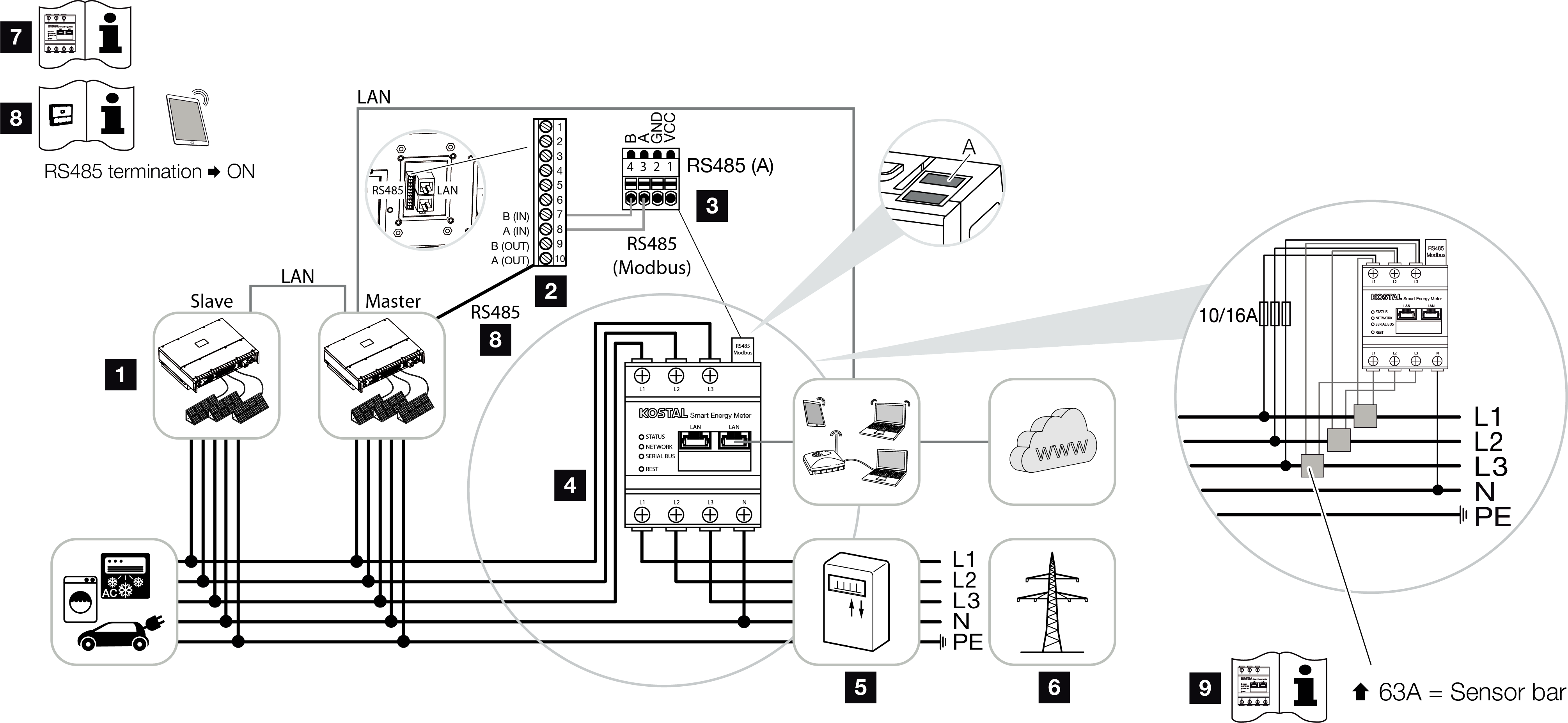
1 | Inverter |
2 | RS485 interface for inverter |
3 | RS485 interface for KOSTAL Smart Energy Meter |
4 | KOSTAL Smart Energy Meter |
5 | Feed meter |
6 | Public grid |
7 | Read the operating manual of the KOSTAL Smart Energy Meter. |
8 | Set RS485 termination in the KOSTAL PIKO CI app to ON |
9 | Use a current transformer for currents above 63 A. Read the operating manual of the KOSTAL Smart Energy Meter. |
Connecting the KOSTAL Smart Energy Meter
- De-energise the mains cable.
DANGER
Risk of death due to electrical shock and discharge!
De-energise all devices and secure them against being switched on again.
- Install the KOSTAL Smart Energy Meter as shown in the illustrations at the grid connection point in the house grid.
- Correctly route the communication cable from the inverter to the control cabinet and connect to the KOSTAL Smart Energy Meter following the wiring diagram provided by the manufacturer.
INFO

Requirements of communication cable:
- Wire cross-section from 0.34 to 1.5 mm² (rigid) or 0.34 to 1.0 mm² (flexible)
- Bus length max. 1000 m
- Length of stripped insulation approx. 5 mm
- Feed the communication cable through the cover of the inverter for COM2 connection panel. Seal connection with sealing ring and union nut.

- Connect the communication cable to the plug connector for the communication interface. Note the pin assignment.
Torque: 0.2 Nm. - Connect the plug connector on the inverter to communication interface in COM2 connection panel.
- Establish a LAN connection from the KOSTAL Smart Energy Meter and the inverter to the Internet.
- In this variant, the KOSTAL Smart Energy Meter works as a slave and sends data to the inverter.
- In the KOSTAL Smart Energy Meter, select the KOSTAL PIKO CI for the RS485 A interface. Please refer to the operating manual of the KOSTAL Smart Energy Meter.
- Mount COM2 cover cap.
Torque: 1.5 Nm
After commissioning, the following settings still have to be configured in the KOSTAL PIKO CI app.
- The use and installation position of the KOSTAL Smart Energy Meter (KSEM) must be set in the KOSTAL PIKO CI app on the Master inverter.
This can be set under Settings > Inverter settings > Power adaptation/controls > Energy management > Power limitation function > KSEM and Settings > Inverter settings > Power adaptation/controls > Energy management > Sensor position > Grid connection point (default value). - A power limitation of the grid feed-in (e.g. to 70%) must be entered in watts on the Master inverter.
This can be set under Settings > Inverter settings > Power adaptation/controls > Energy management > Limitation of the active power to [W]. INFO
If power limitation is carried out in combination with the KOSTAL Smart Energy Meter, power limitation via a ripple control receiver (RCR) is not possible and must be deactivated.
- The inverter to which the KOSTAL Smart Energy Meter has been connected must be configured as the Master.
This can be selected under Settings > Communication settings > Master/Slave settings > Master RS485. - On the Master inverter connected to the RS485 communication line, set the RS485 termination to ON in the KOSTAL PIKO CI app.
This can be done under Settings > Communication settings > RS485 Settings > Terminating resistor. - All other inverters connected to the master inverter via LAN must be configured as Slave. The following default settings should be checked for all slave inverters:
Master/slave settings: Slave
Power limitation function: deactivated
Sensor position: Grid connection point
Activate ripple control receiver: OFF
- Inverter connected to the KOSTAL Smart Energy Meter .