Connecting central grid and system protection
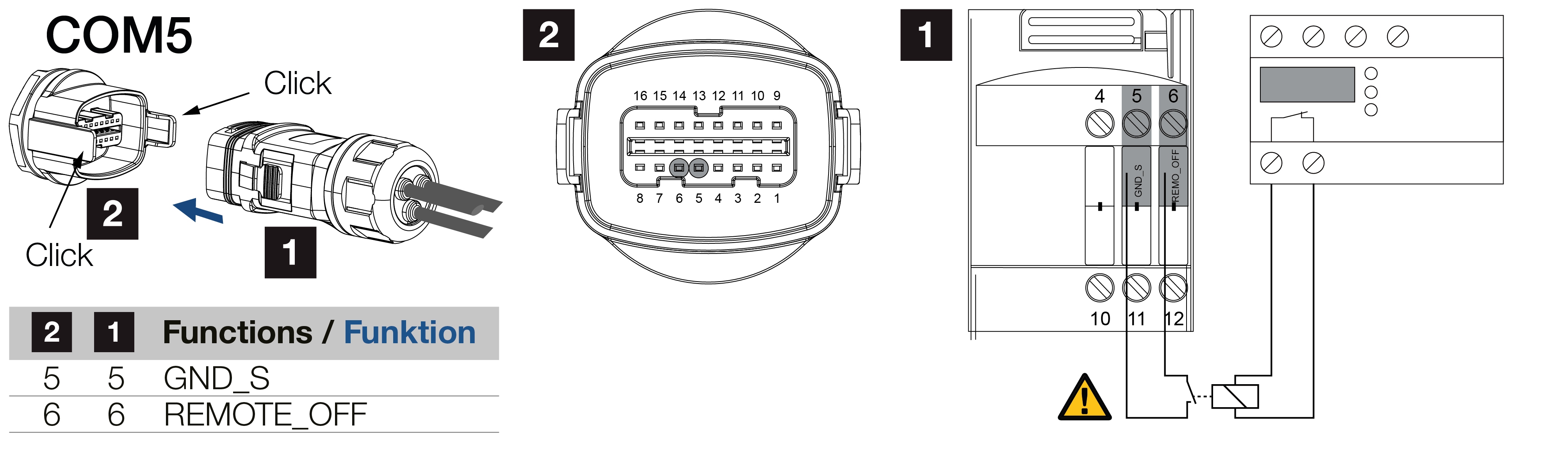
1 | COM plug |
2 | Inverter COM connection |
3 | Grid and system protection - Switch closed: Feed-in, Switch open: Feed-in prevented |
4 | Activation of grid and system protection via KOSTAL PIKO CI app |
5 | Relay in the event of great distances |
Central grid and system protection is required in some countries. This monitors the voltage and frequency in the grid and in the event of a fault, shuts down the photovoltaic systems by means of a circuit breaker.
If your energy supplier requires central grid and system protection for your system, install an external monitoring device, which switches off the inverter via a normally open or normally closed contact. An additional circuit breaker is not required as this is replaced with the internal switches in the inverter.
Connection
DANGER
Risk of death due to electrical shock and discharge!
De-energise all devices and secure them against being switched on again.
INFO

Requirements of communication cable:
- wire cross-section from 0.34 to 1.5 mm² (rigid) or 0.34 to 1.0 mm² (flexible)
- length of stripped insulation approx. 7.5 mm
- Potential bus length max. 1000 m. Follow the manufacturer's specifications on maximum cable length.
POSSIBLE DAMAGE
Remote connection in the inverter may be destroyed!
Only a potential-free contact may be connected to the inverter connection for central mains and system protection; no voltage source may be connected.
- De-energise the mains cable.
- Install the monitoring device in the control cabinet or power distributor.
- If there is a considerable distance between the monitoring unit and the inverter, a relay must be used.
- Correctly route the communication cable from the inverter to the control cabinet and connect following wiring diagram provided by manufacturer.
- Feed the communication cable through the supplied communication plug and seal.
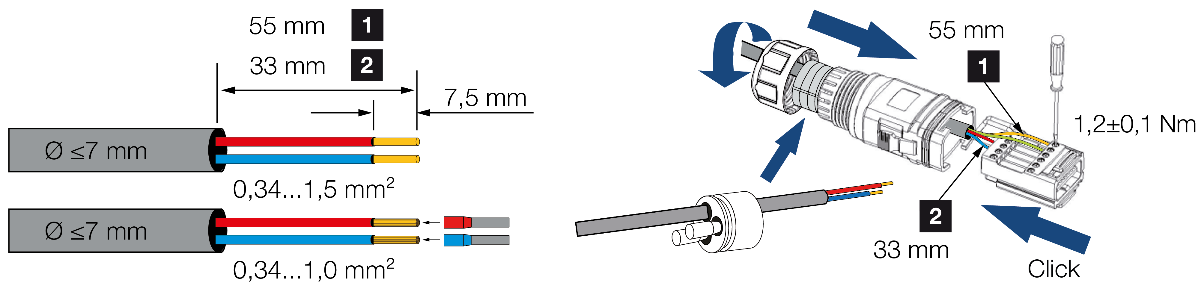
- Connect the communication cable to the inverter plug.
- Assemble the plug and tighten the cap nut to the specified torque.
Tightening torque: 3 Nm. - Plug the connector into the interface in the COM connection panel.
After commissioning
- After commissioning, the function must be activated in each inverter using the KOSTAL PIKO CI Conf App.
This can be activated under Settings > Basic settings > External shutdown > ON.
- Inverter set up for grid and system protection function.
INFO
The external shutdown is not functioning reliably.
If the inverter switches off or does not function perfectly after the external shutdown is activated, the cable to the inverter may be too long.
The cable length can cause the cable resistance to be very high such that it does not fall to 0V. If this is the case, the cable to the inverter must be shortened.