Communication connection for KOSTAL Smart Energy Meter via RS485
1 | Inverter |
2 | RS485 interface for inverter |
3 | RS485 interface for KOSTAL Smart Energy Meter |
4 | KOSTAL Smart Energy Meter |
5 | Feed meter |
6 | Public grid |
7 | Read the operating manual for the KOSTAL Smart Energy Meter |
8 | Set RS485 termination in KOSTAL PIKO CI app to ON |
9 | Use a current transformer for currents above 63 A. Read the operating manual for the KOSTAL Smart Energy Meter |
Connecting the KOSTAL Smart Energy Meter
DANGER
Risk of death due to electrical shock and discharge!
De-energise all devices and secure them against being switched on again.
INFO

Requirements of communication cable:
- wire cross-section from 0.34 to 1.5 mm² (rigid) or 0.34 to 1.0 mm² (flexible)
- length of stripped insulation approx. 7.5 mm
- Potential bus length max. 1000 m. Follow the manufacturer's specifications on maximum cable length.
- De-energise the mains cable.
- Install the KOSTAL Smart Energy Meter as shown in the illustrations at the grid connection point in the house grid.
- Correctly route the communication cable from the inverter to the control cabinet and connect to the KOSTAL Smart Energy Meter following the manufacturer's wiring diagram.
- De-energise the inverter. Switching off the inverter
- Guide the RS485 cable through the communication plug and seal provided.
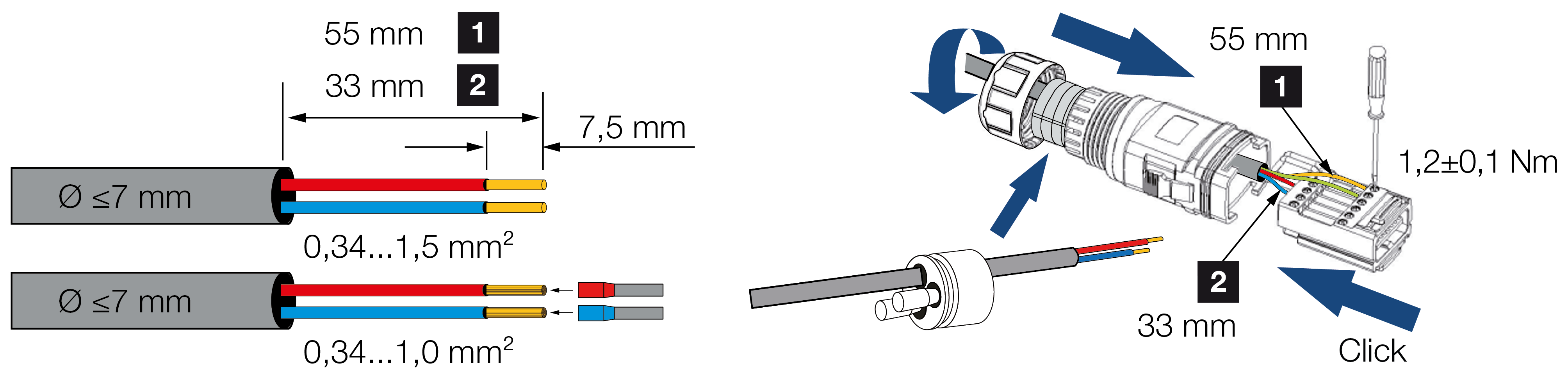
- Fit RS485 cable on inverter plug.
- Assemble plug and tighten union nut to the prescribed tightening torque.
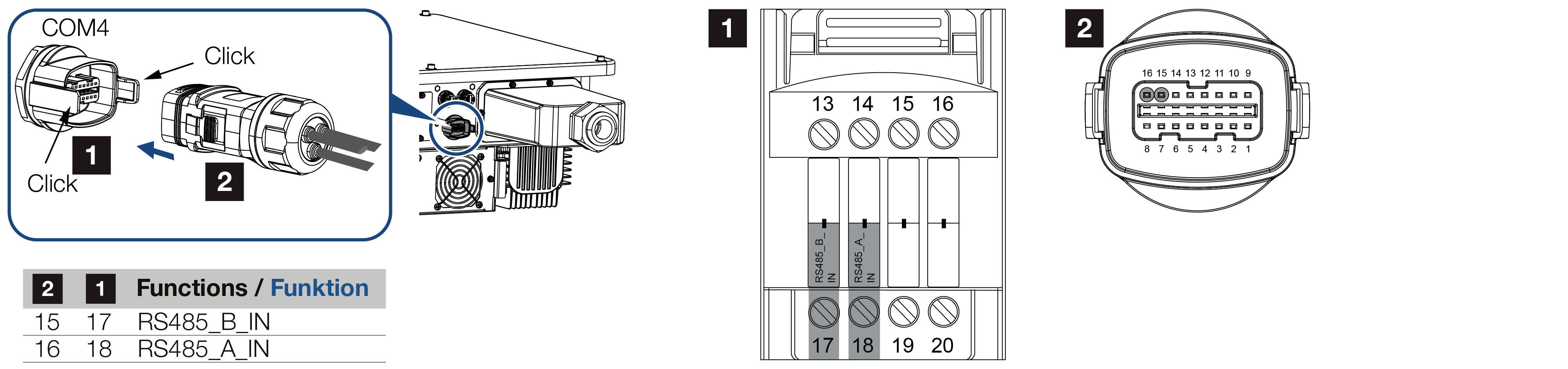
Tightening torque: 3 Nm. - Connect the plug to the interface in the COM connection panel.
- Establish a LAN connection from the KOSTAL Smart Energy Meter and the inverter to the Internet.
- Inverter connected to KSEM.
After commissioning
After commissioning, the following settings still have to be configured in the KOSTAL PIKO CI Conf App.
This includes elements, such as the RS485 connection setting.
Configuring settings using the KOSTAL Smart Energy Meter user interface
- In the KOSTAL Smart Energy Meter, go to Modbus settings and select the PIKO CI to the RS485 A interface. Please refer to the operating manual of the KOSTAL Smart Energy Meter.
In this variant, the KOSTAL Smart Energy Meter works as a slave and sends data to the inverter.
Configuring settings using the KOSTAL PIKO CI App
- On the master inverter to which the RS485 communication cable is connected, set RS485 termination in the KOSTAL PIKO CI Conf App to ON.
This can be done under Settings > Communication settings > RS485 settings > Terminal resistor. - Use of the KOSTAL Smart Energy Meter (KSEM) must be configured in the KOSTAL PIKO CI Conf App on the master inverter.
For this purpose, go to Settings > Inverter settings > Power adaptation/control > KSEM management > Activate/deactivate KSEM > Activate. - The connection between KSEM and inverter is set by going to Settings > Inverter settings > Power adaptation/control > KSEM management > Connection between KSEM and master inverter > RS485.
- The installation position is set by going to Settings > Inverter settings > Power adaptation/control > KSEM management > Sensor position > Grid connection point.
- The KSEM modbus address is set by going to Settings > Inverter settings > Power adaptation/control > KSEM management > Energy meter modbus address > 1 (standard value in KSEM).
- A power limitation of the grid feed-in (e.g. to 70%) must be entered in watts on the Master inverter.
The active power limitation is entered by going to Settings > Inverter settings > Power adaptation/control > KSEM management > Limitation of the active power to (W). - All other inverters connected to the master inverter by LAN are configured as slave. Do not configure any further settings in slave inverters.
- Inverters configured.