System overview
The PLENTICORE G3 is a three-phase hybrid inverter, which can be used in three-phase grids.
The inverter can be used as follows.
As a PV inverter
If the inverter is used as a pure PV inverter, only PV generators are connected to the DC inputs. There must be at least one PV generator connected to the inverter.
The energy generated can be used for self-consumption in the house grid or is fed into the public grid.
1 | Communication link for inverter via LAN |
2 | Communication link for inverter via WLAN/WiFi |
3 | Inverter |
4 | PV generators |
5 | Line circuit breaker for inverter |
6 | Digital energy meter (Modbus RTU) at the grid connection point |
7 | Main fuse for building |
8 | Procurement and feed meter or smart meter (not in all countries) |
9 | Public grid |
10 | Line circuit breaker for energy consumers |
11 | Energy consumers |
Hybrid inverter (product upgrade required)
If the inverter is being used as a hybrid inverter, PV generators and a battery are connected to the inverter.
For the battery to be detected at the DC input for the battery, the battery function product upgrade must be activated in the inverter using an activation code.
The inverter is used to directly provide energy for self-consumption or to store surplus energy in the battery storage unit. The stored energy can be used for self-consumption in the house grid. Surplus energy that can no longer be stored is fed into the public grid.
In addition, energy from other AC energy suppliers (park controllers), e.g. PV systems, combined heat and power (CHP) units or small wind turbines, can be temporarily stored.
1 | Communication link for inverter via LAN |
2 | Communication link for inverter via WiFi/WLAN |
3 | Inverter |
4 | PV generators |
5 | Connection for battery system (available as option after activation) |
6 | Communication link for battery management system |
7 | Line circuit breaker for inverter |
8 | Digital energy meter (Modbus RTU) at the grid connection point |
9 | Main fuse for building |
10 | Procurement and feed meter or smart meter (not in all countries) |
11 | Public grid |
12 | Line circuit breaker for energy consumers |
13 | Energy consumers |
14 | Feed meter for AC power source |
15 | Line circuit breaker for AC power source |
16 | AC power source, e.g. combined heat and power (CHP) unit, or other generation plants, such as PV inverter (the energy from the AC power source can be temporarily stored in the battery) |
Battery inverter (product upgrade required)
If the inverter is used as a pure battery inverter, a battery can be connected to the last DC input (BAT).
For the battery to be detected at the DC input for the battery, the battery function product upgrade must be activated in the inverter using an activation code.
The inverter with connected battery storage is used to store energy from energy suppliers (park controllers) produced in the house grid, e.g., by other PV systems, combined heat and power (CHP) units or small wind turbines. The stored energy can then be used for self-consumption in the house grid.
There is the option to connect PV generators to the free DC inputs (hybrid inverter).
1 | Communication connection to inverter via LAN |
2 | Communication connection to inverter via WiFi/WLAN |
3 | Inverter |
4 | Battery system connection |
5 | Communication connection: Battery management system (BMS) via RS485 |
6 | Circuit breaker Inverter |
7 | Digital energy meter (Modbus RTU) at the grid connection point |
8 | Main fuse, house |
9 | Consumption and feed-in meter or smart meter (not available in all countries) |
10 | Public grid |
11 | Circuit breaker Electricity consumption |
12 | Electricity consumption |
13 | Feed-in meter AC energy supplier |
14 | Circuit breaker for AC energy supplier |
15 | AC power source, e.g. CHP unit, or other generation systems (EZA), e.g. PV inverter (the energy from the AC power source can be temporarily stored in the battery) |
Inverter with KOSTAL Wallbox ENECTOR via KSEM
If the inverter and a KOSTAL ENECTOR wallbox with comfort function are installed in the system environment, a KOSTAL Smart Energy Meter (KSEM) must be used as the energy meter.
The KSEM is a three-phase energy meter that controls the wallbox and the inverter via an RS485 connection.
In this case, the entire system cannot be controlled via an MDC host inverter.
1 | Communication link for inverter via LAN |
2 | Communication link for inverter via WiFi/WLAN |
3 | Inverter |
4 | PV generators |
5 | Connection for battery system (available as option after activation) |
6 | Communication link for battery management system |
7 | Line circuit breaker for inverter |
8 | KOSTAL Smart Energy Meter (Modbus RTU) at the grid connection point |
9 | Main fuse for building |
10 | Procurement and feed meter or smart meter (not in all countries) |
11 | Public grid |
12 | Line circuit breaker for energy consumers |
13 | Energy consumers |
14 | Communication link for ENECTOR wallbox |
15 | Line circuit breaker for ENECTOR wallbox |
16 | ENECTOR wallbox |
Controlling inverters via Multi Device Control (MDC)
This function is available from PLENTICORE G3 SW 3.06.10 onwards.
Further information on configuration and wiring can be found in the supplementary document Wiring and setting up multiple KOSTAL inverters via MDC.
Multi Device Control (MDC) enables central monitoring and control of MDC-enabled inverters and other MDC-enabled devices within the same home network. The control function is performed by a PLENTICORE G3 inverter configured as an MDC host. The MDC host inverter can be operated both without a battery and with a connected battery. If a battery is used within the MDC system network, it must be connected to the MDC host inverter. The battery with the largest usable capacity must be connected to the MDC host.
If several PLENTICORE G3 inverters with batteries have been installed in the home network, these are controlled via an MDC host. To do this, the paid product extension / add-on option ‘Battery Control with MDC’ must be activated on the MDC host inverter. If several batteries have been installed in the MDC system network, the battery with the largest capacity must be connected to the MDC host inverter.
Without the ‘Battery Control with MDC’ product extension, only one battery can be connected to and controlled via the MDC host inverter.
Controlling and regulating other MDC client inverters is also possible without the product extension if only one battery storage unit is used in the MDC system.
An energy meter (KEM) can be used as the energy meter in this configuration. A KOSTAL Smart Energy Meter (KSEM) is not strictly necessary.
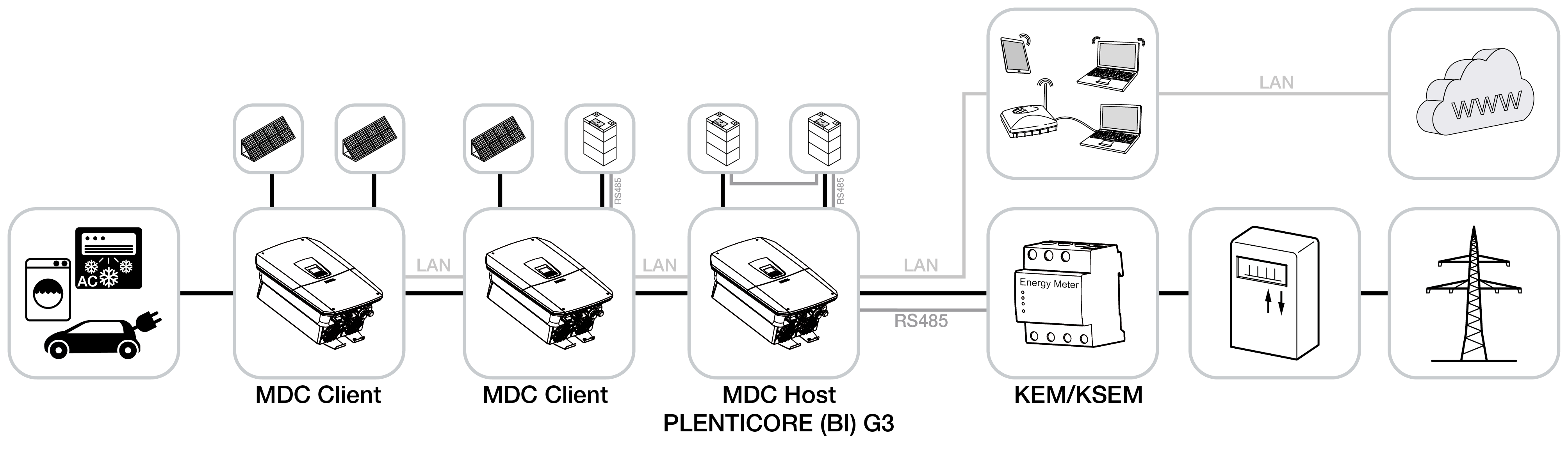
Inverters configured as MDC client inverters can be added via the device manager in the MDC host inverter. These devices are then displayed in the power flow diagram under ‘Instantaneous values’ on the MDC host inverter.
INFO

If non-MDC-capable devices are present in the same home network alongside MDC-capable devices and need to be controlled together, this can only be done via a KOSTAL Smart Energy Meter and not via an MDC host inverter.
This is the case, for example, if a PLENTICORE G3 and a PLENTICORE plus G1 or an ENECTOR wallbox with comfort function, which is controlled via Modbus RTU (RS485), have been installed in the home network.
Product extensions
Product extensions can be activated using activation codes. PLENTICOINs are required for this.
The PLENTICOIN is a single-purpose voucher for product extensions. The PLENTICOIN can be redeemed in the KOSTAL Solar Webshop for the required activation code (e.g. battery extension). The PLENTICOIN is purchased from specialist wholesalers.
The following product extensions are available and can be accessed at KOSTAL Solar Webshop using the PLENTICOIN:
The product upgrades can then be activated using the KOSTAL Solar App, the inverter display or the inverter Webserver by going to Additional options and entering the activation code.
- Battery upgrade
Allows a battery to be connected to the DC input for the battery. - Power upgrade
Increases the inverter’s basic power by up to two levels - Battery control with MDC
Enables the control of multiple batteries in a system network. A maximum of 3 inverters with batteries can be controlled via MDC. The product extension Battery control with MDC only needs to be activated on the MDC-HOST.
Power classes
The inverter is available in three sizes, S, M and L, with a basic power level of 4.0 to 20 kW.
The basic power level can be increased by two levels using an optional product upgrade (power upgrade) to make system planning as flexible as possible.
The power upgrade can also be done later, without having to replace the inverter.
The power activated in the inverter can be marked on the type plate. The activated power is also shown in the inverter's parameter report, available from the Webserver, and on the inverter's display.
Size | Basic power | Level 1 | Level 2 |
|---|---|---|---|
PLENTICORE S G3 | 4.0 | 5.5 | 7.0 |
PLENTICORE M G3 | 8.5 | 10 | 12.5 |
PLENTICORE L G3 | 15 | 17.5 | 20 |
Further information can be found at Technical data