Backup switch connection (optional)
If a battery is connected to the inverter, the inverter offers the option of continuing to supply the house grid with energy using the PV and battery should the mains supply fail.
For this purpose, a manual or automatic backup box must be installed in the house grid at the grid connection point.
KOSTAL offers the KOSTAL BackUp Switch as a manual variant, which disconnects the public grid from the house grid in backup mode.
Automatic backup boxes are offered as accessories by other suppliers.
You will find a list of approved KOSTAL Solar Electric accessories on our website in the download area for the product.
Connection of communication cable in the inverter for the KOSTAL BackUp Switch
System overview
The KOSTAL BackUp Switch is connected differently depending on the country and the energy supplier. Ask your energy supplier which type of connection you require.
Left: Neutral point setup required. Separation of the neutral conductor from the public grid with the KOSTAL BackUp Switch in backup mode.
Right: Neutral point setup not required. No neutral conductor separation from the public grid with the KOSTAL BackUp Switch in backup mode.
1 | KOSTAL BackUp Switch |
2 | Consumers in grid mode and backup mode |
3 | Consumers in grid mode |
INFO

The communication cable is subject to the following requirements:
Conductor cross-section from 0.2 to 1.5 mm2
Max. length 30 m
Length of stripped insulation 8 mm
Observe the specifications for cable cross-sections in the manufacturer's instructions.
- Follow the supplied instructions for the KOSTAL BackUp Switch.
- Switch the DC switch on the inverter to OFF.
- De-energise the house grid and secure it against being switched back on.
- Install the KOSTAL BackUp Switch on the top-hat rail in the control cabinet or power distributor.
- Lay the backup signal cable correctly from the inverter into the control cabinet and connect it to the KOSTAL BackUp Switch.
- Connect the backup signal cable in the inverter to the terminal for the backup function (terminal X402).
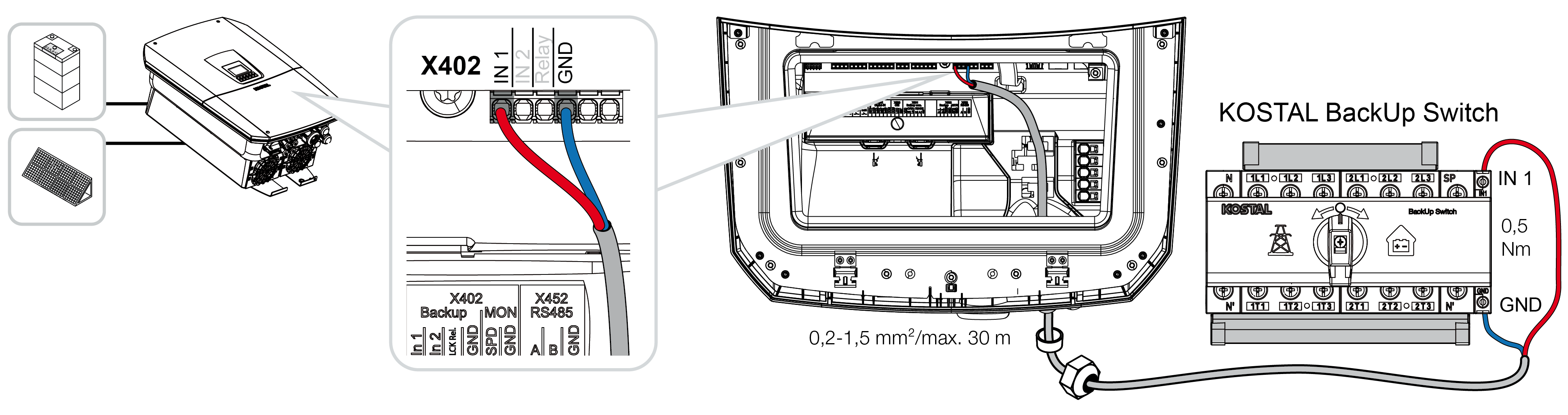
- The KOSTAL BackUp Switch signal cable is connected.
Use of the KOSTAL BackUp Switch is selected when the inverter is initially installed, or it can be selected via the Webserver by going to Service menu – General > Operating mode > Change operating mode.
Connection of the communication cable in the inverter for the automatic backup box
System overview
The connection may be different depending on the country, grid connection, energy supplier and backup box manufacturer. Therefore, follow the backup box manufacturer's specifications precisely.
1 | Backup box |
2 | Consumers in grid mode and backup mode |
3 | Consumers in grid mode |
INFO
The communication cable is subject to the following requirements:
Conductor cross-section from 0.2 to 1.5 mm2
Max. length 30 m
Length of stripped insulation 8 mm
Observe the specifications for cable cross-sections in the manufacturer's instructions.
- Follow the supplied instructions for the backup box.
- Switch the DC switch on the inverter to OFF.
- De-energise the house grid and secure it against being switched back on.
- Mount and install the automatic backup box in the house network in accordance with the manufacturer's specifications.
- Route the backup signal cable correctly from the inverter to the automatic backup box and connect it to the backup box in accordance with the manufacturer's connection plan.
- Connect the backup signal cable in the inverter at the terminal for the backup box (terminal X402).
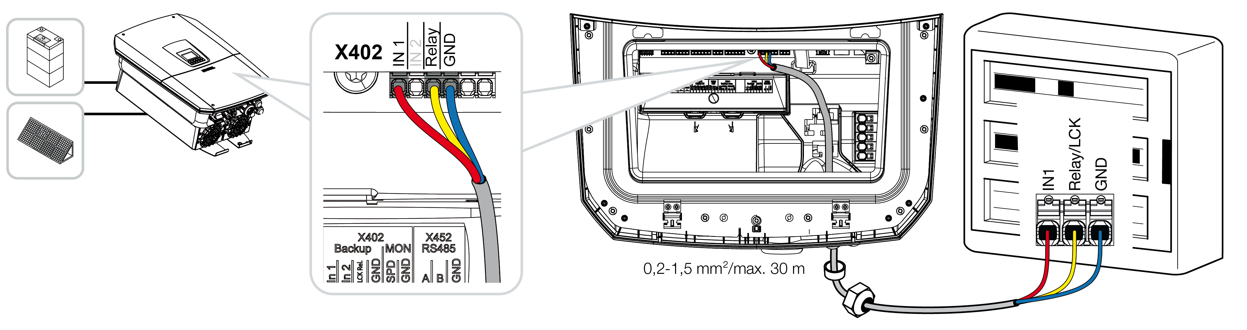
- The automatic backup box's signal cable is connected.
Use of the automatic backup box is selected when the inverter is initially installed, or it can be selected via the Webserver by going to Service menu – General > Operating mode > Change operating mode.