Connecting the signal contact for the external overvoltage protection (SPD – Surge Protective Device)
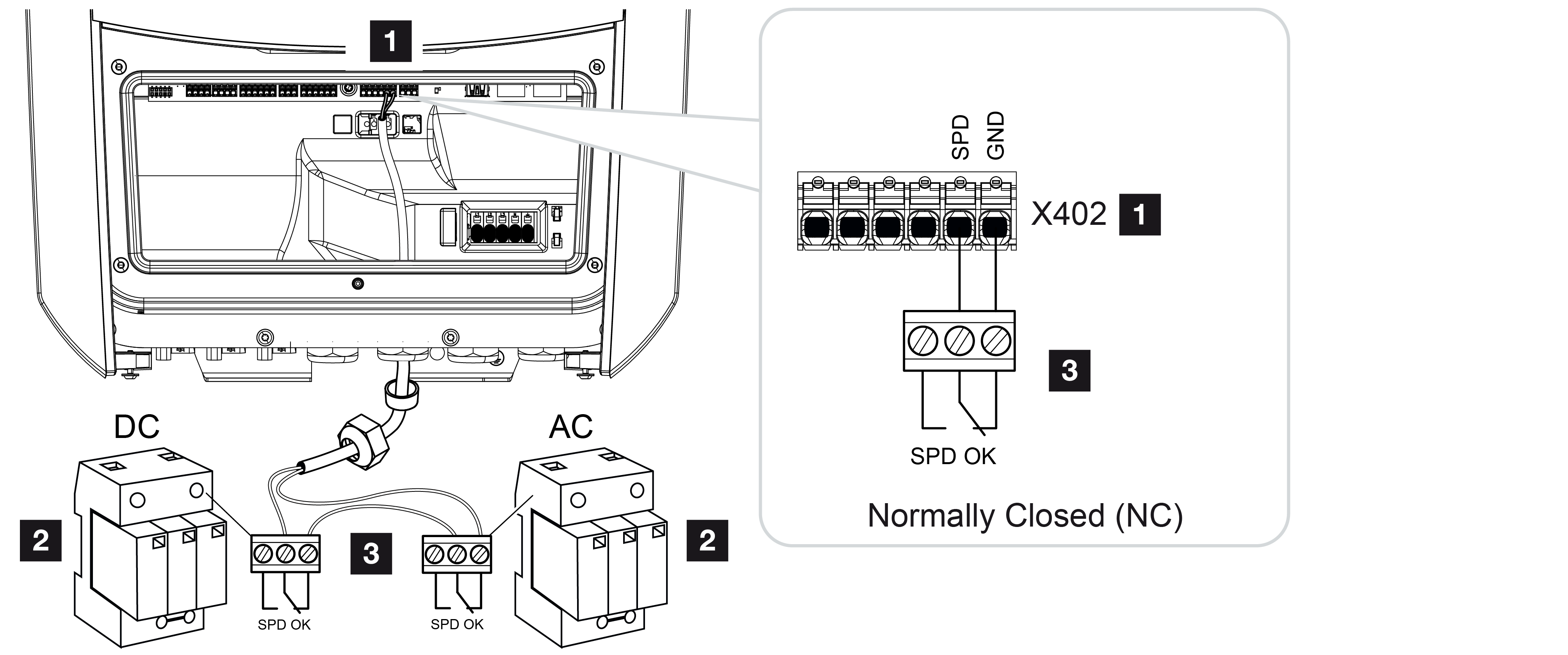
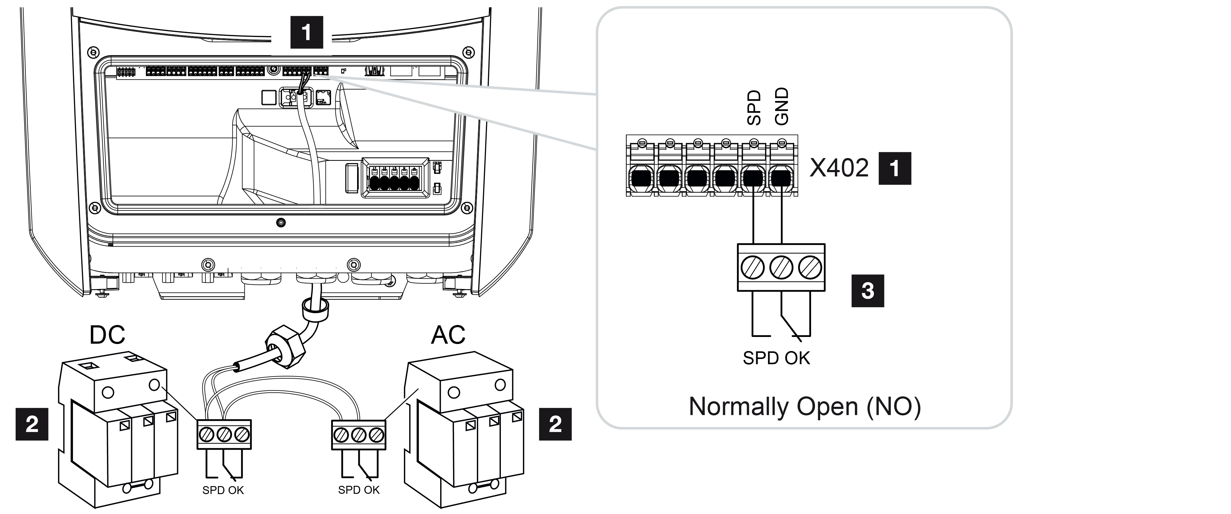
1 | Connection terminal X402 for Smart Communication Board (SCB) |
2 | Surge protection devices (SPD) for AC and DC side |
3 | Control line from SPD to inverter |
To protect the PV system from overvoltages, overvoltage protection (SPD type 2) should be installed on the DC side between the inverter and the PV generator and on the AC side between the inverter and the grid.
The inverter can evaluate the message output of the overvoltage modules (SPD) and output a message if an event occurs. The cable is connected without potential to the inverter's terminal X402 by the SPD After commissioning the inverter, the overvoltage protection must be configured in the Webserver as normally open (NO) or normally closed (NC).
Perform the following steps
- De-energise the house grid.
DANGER
Risk of death due to electrical shock and discharge!
De-energise device and secure against being switched on again. De-energising the inverter
- Install the surge protection device (SPD) for AC and DC in the control cabinet or power distributor.
- Correctly route the signal cable from the inverter to the control cabinet and connect to the SPD following the wiring diagram provided by the manufacturer.
With two SPDs, pay attention to how the signal cables are connected to each other: Series (for NC) or parallel (for NO). INFO

The signal cable is subject to the following requirements:
Conductor cross-section from 0.2 to 1.5 mm2
Max. length 30 m
Length of stripped insulation 8 mm
Observe the specifications for cable cross-sections in the manufacturer's instructions.
- Connect the communication cable in the inverter to terminal X402 for the surge protection device.
- Once the inverter has undergone initial commissioning, the overvoltage protection must still be configured in the Webserver. Webserver menu – Service menu – General
- The overvoltage protection is connected.