Connection for self-consumption control
The inverter offers the option of connecting consumers to the inverter via an external load relay or directly to the switched outputs (e.g. OUT1).
If the PV or grid excess power is sufficiently high, the switched output is then switched on to access the PV energy that is currently being generated.
Connection options:
- Use of a load relay to decouple and control 230 V loads.
- Direct connection to the digital input's switched output, e.g. for a heat pump or wallbox or to the input module of a smart home system.
Check which connection method is required for the device. For more information, please refer to the manual of the device to be controlled.
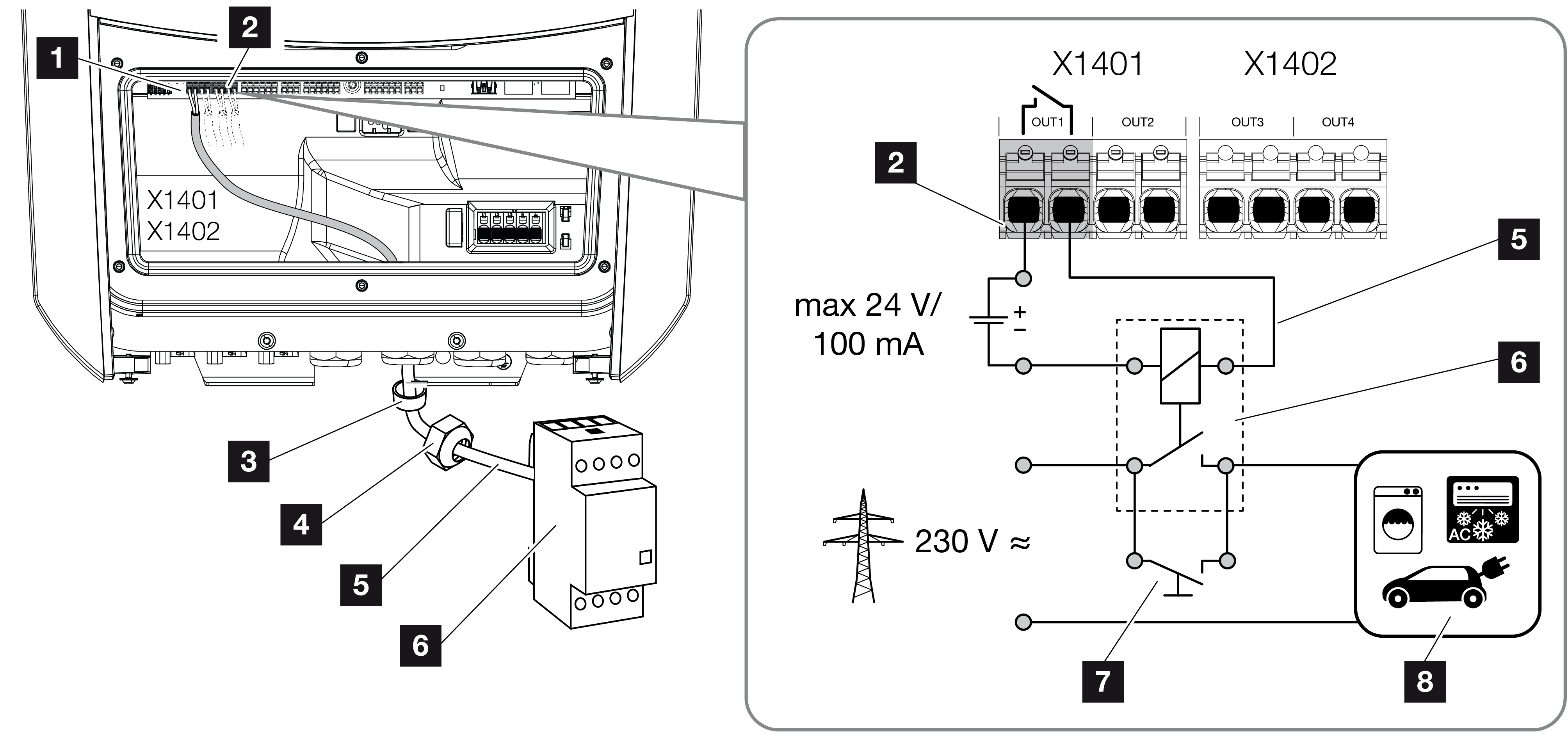
Connection example with load relay:
- Load control operating mode: Here, an external load (e.g. washing machine or air conditioning system) is triggered.
- Events operating mode: As soon as an event is present, an external load (e.g. lamp or signal horn) is triggered.

1 | Smart Communication Board (SCB) |
2 | Terminal for self-consumption control |
3 | Sealing ring |
4 | Union nut |
5 | Control line |
6 | Load relay/connection via potential-free contact |
7 | Jumper switch |
8 | Consumer device |
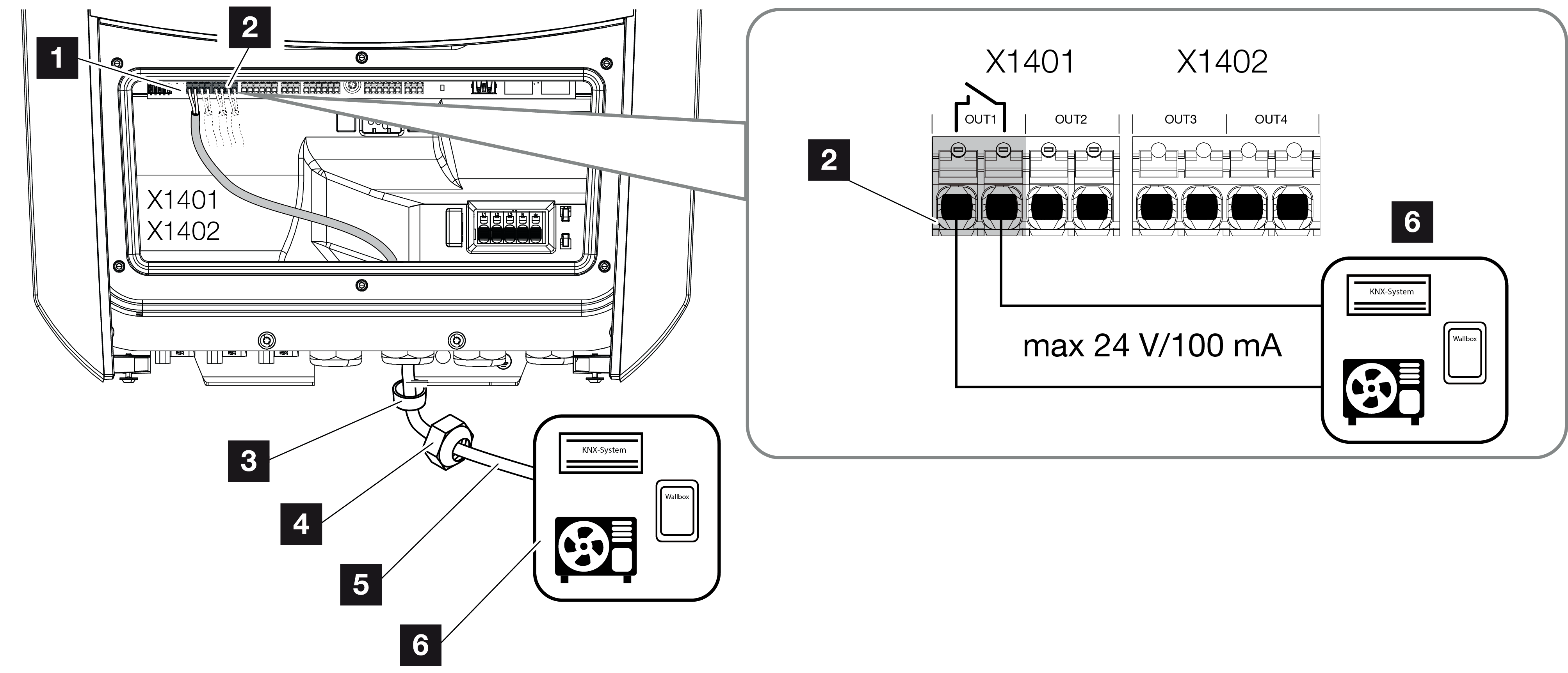
Connection example, direct connection to the switched output via potential-free contact:
- SG Ready operating mode: Here, the switching signal (e.g. contact closes) for using the PV energy is transferred directly to the heat pump's digital input.
- Wallbox operating mode: The charging process is started as soon as the contact is closed. The wallbox offers a digital/signal input for this purpose.
- Events/external control operating mode: The external device is controlled via a digital/signal input. This can be, for example, a KNX control unit or another smart home system.

1 | Smart Communication Board (SCB) |
2 | Terminal for self-consumption control |
3 | Sealing ring |
4 | Union nut |
5 | Control line |
6 | Consumer device |
For the electrical connection of the self-consumption control, proceed as follows:
INFO

If loads need to be switched and require a higher load at the switched output than 24 V/100 mA, an external load relay must be installed between the inverter and the consumer. No consumers may be connected directly to the inverter.
In the case of loads or consumers that are controlled via a potential-free switching contact (e.g. SG-ready heat pump control or smart home systems), these consumers can be connected directly to the switched output.
Switched output load, potential-free:
Max. load: 100 mA
Max. voltage: 24 V (DC)
- De-energise the house grid.
DANGER

Risk of death due to electrical shock and discharge!
De-energise device and secure against being switched on again. De-energising the inverter
- Connect the load relay professionally or connect the consumer to the self-consumption control terminal on the Smart Communication Board.
INFO

The signal cable is subject to the following requirements:
Conductor cross-section from 0.2 to 1.5 mm2
Length of stripped insulation 8 mm
- Properly install and connect the other components of self-consumption control.
- The electrical connection for self-consumption control has been made. Switch on the inverter.