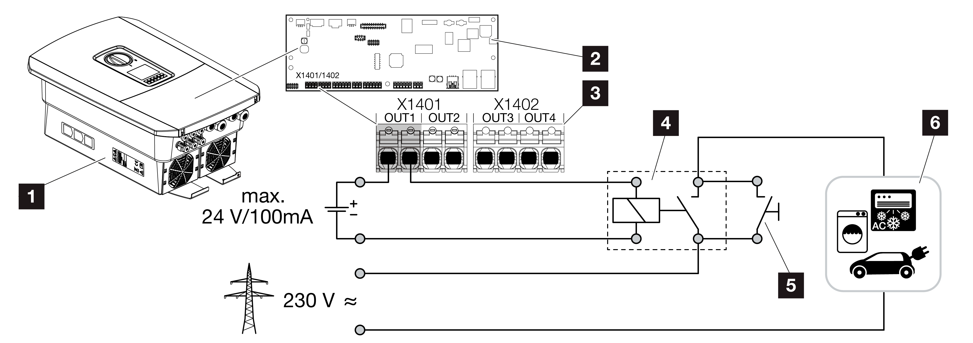
Connection of switched outputs
|
1 |
Inverter |
|
2 |
Smart Communication Board |
|
3 |
Terminal with four switched outputs (OUT 1-4) |
|
4 |
Load relay |
|
5 |
Jumper switch |
|
6 |
Consumers/actuators |
The inverter allows consumers to be connected to it via an external load relay, which can be switched on when there is sufficient PV or grid surplus feed-in power and thereby use the PV energy generated at that point in time.
If there is an event message, the inverter can trigger an actuator connected to the switched output (warning light, message signal, smart home system), providing information about the event that occurred.
INFO

The communication cable is subject to the following requirements:
Wire cross-section from 0.2 to 1.5 mm2
Length of stripped insulation 8 mm
More information about connection and configuration Switched outputs.