Connecting the mains cable
- Disconnect the house network from the power supply.
DANGER
Risk of death due to electrical shock and discharge!
De-energise device and secure against being switched on again. De-energising the inverter
- Secure the house fuses against being switched back on.
- Switch the DC switch on the inverter to Off.
- Remove the screws from the lower cover and take off the cover.
IMPORTANT INFORMATION

When working inside the inverter, only use insulated tools to prevent short circuits.

- Remove the screws from the connection compartment and take off the cover.

- Lay the power cable from the power distributor to the inverter in a professional manner.
IMPORTANT INFORMATION
For the dimensioning of the required AC circuit breaker, see Technical data.
Single-core cables (type NYY-J or NYM-J) without ferrules can be used with the AC connection terminal.
When using fine-stranded cables (type H05../H07RN-F), wire end ferrules must be used. Ensure that the contact length is 18 mm.

- Insert the mains cable (2) into the inverter and seal it with the sealing ring (3) and union nut (4). Tighten the union nut to the specified torque. Tightening torque: 8 Nm (M25).
- Leave the sealing ring in the screw connections that are not being used.
- Connect the wires of the mains cable to the AC connection terminal (1) according to the labelling.
IMPORTANT INFORMATION
The inverter has spring-loaded terminal strips for connecting the AC cables. Insert the wires into the large round openings (item 1) of the connection terminal. The stripping length is 18 mm. Use wire end ferrules for stranded cables.

- Install a circuit breaker in the grid connection cable between the inverter and the feed-in meter to protect against overcurrent.
CAUTION
Risk of fire due to overcurrent and heating of the mains cable
If mains cables are too small, they can heat up and cause a fire.
- Use a suitable cross-section.
- Install line circuit breaker to secure against overcurrent.
IMPORTANT INFORMATION
This product may cause direct current in the external protective earth conductor. A type A or B ≥ 300 mA residual current device (RCD) can be used on the AC side. The use of a type A RCD is enabled in the web server under Service > General > External hardware settings > Residual current devices. (Default setting: RCD type A enabled).
- In countries where a second PE connection is required, connect it to the marked location on the housing (outside).
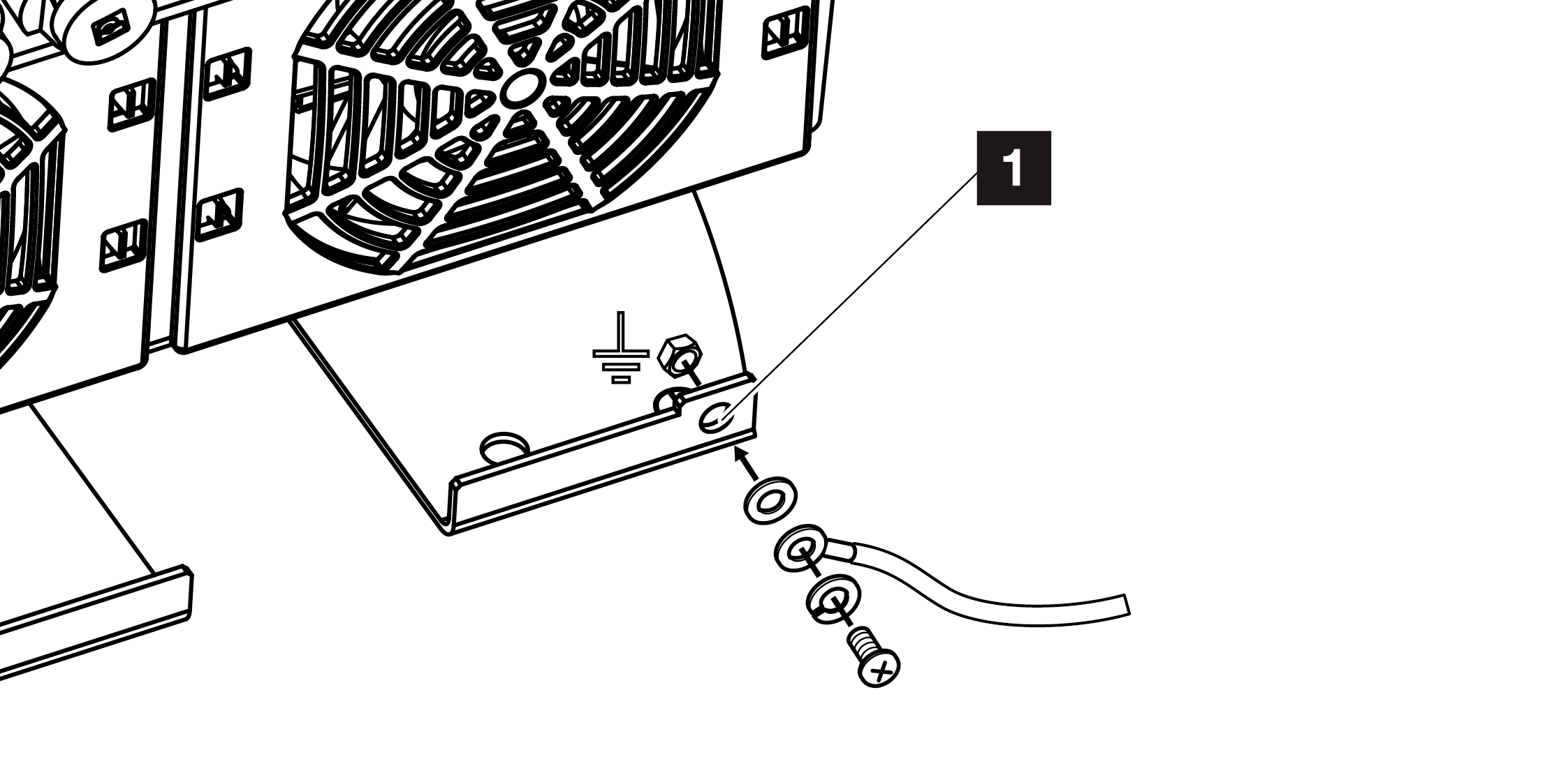
- The AC connection is now complete.