Connecting an optional downgrade input
If the maximum grid connection current is not available in certain circumstances or at certain times, the charging current can be reduced via the downgrade input in the wallbox. The percentage reduction is prescribed via the DIP switches in the wallbox.
The downgrade input can be controlled, for example, by means of the following criteria or control systems:
- Electricity tariff (via external control)
- Time
- Load shedding control
- Manual control
- External load management
Upon delivery, the downgrade input is controlled as follows:
State of switching contact | State of downgrade |
|---|---|
open | Downgrade active |
Closed (NC) | Downgrade not active (default) |
Connecting downgrade input
POSSIBLE DAMAGE

Damage to property from improper installation
Improper installation of the switching contact may result in damage or the product not functioning correctly. Note the following requirements during installation:
- Choose appropriate wiring so that interference is avoided.
Upon delivery, a bridge is used at the downgrade input. The downgrade input is permanently closed as a result. This bridge first has to be removed.
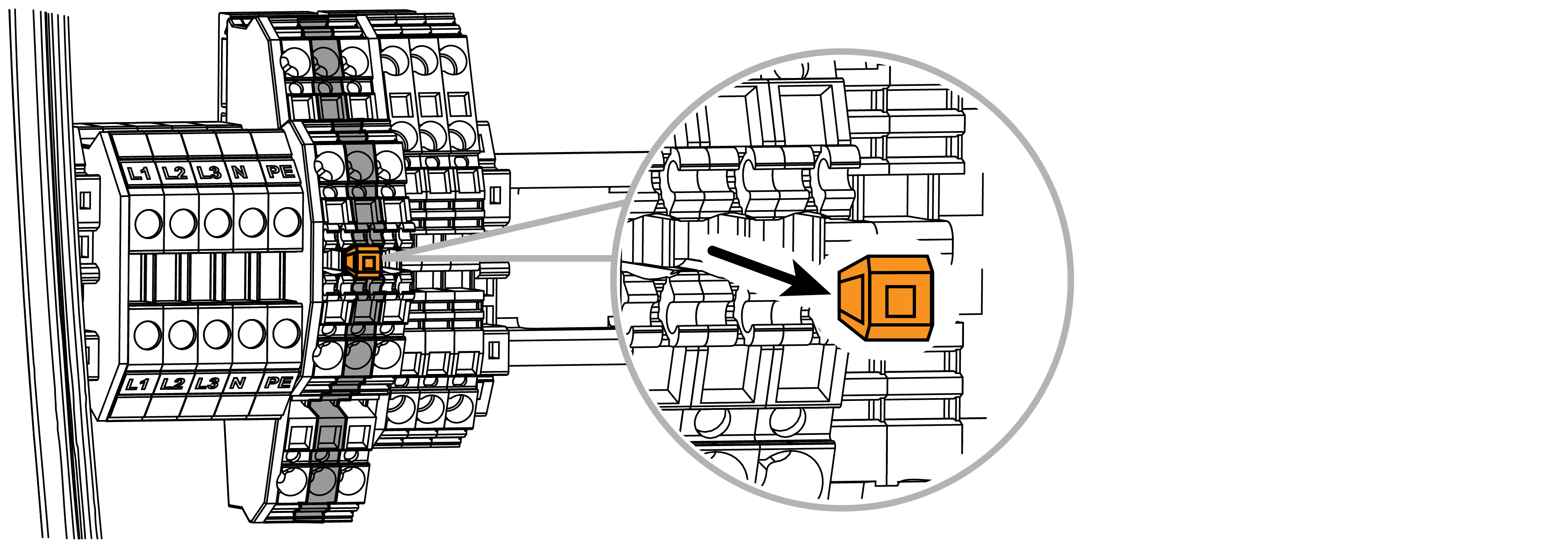
- Removing the bridge
- Install the external switching contact in the building’s junction box. This may be an external control. Note that it is a potential-free switching contact (NC).
- Route the cable between the wallbox and external switching contact.
Note connection data for downgrade input.
- Clamping area rigid / flexible 0.5- 4 mm²
- Clamping area with core end sleeves 0.5 - 2.5 mm² DANGER
Risk of death due to electrical shock and discharge!
If the cable is not kept reliably separate from active electrical equipment, touchable parts may be live. As a result, people may be seriously injured or killed by electric shock.
When routing and connecting the cable, keep it reliably separate from active electrical equipment.
- Use a suitable to tool to cut the required cable inlet out of the wallbox. Cable inlets are located on the rear, bottom and top.
- Insert the appropriate membrane cable entry (included in the scope of delivery) into the respective cable inlet.
For cable inlet on the top or bottom: Use membrane cable entries with strain relief.
For cable inlet on the rear: Use membrane cable entries without strain relief. - Insert the cables into the wallbox. To do this, a hole must be pierced in the membrane.
INFO

To prevent rainwater from entering, the hole in the membrane should not be any larger than the cables.
- Strip the cable.
- Strip 10 mm of insulation from the wires.
- Connect cable to terminal 3 and 4 on wallbox according to terminal labelling.
INFO
The potential-free contact can be loaded to max. 12 V DC / 8 mA.
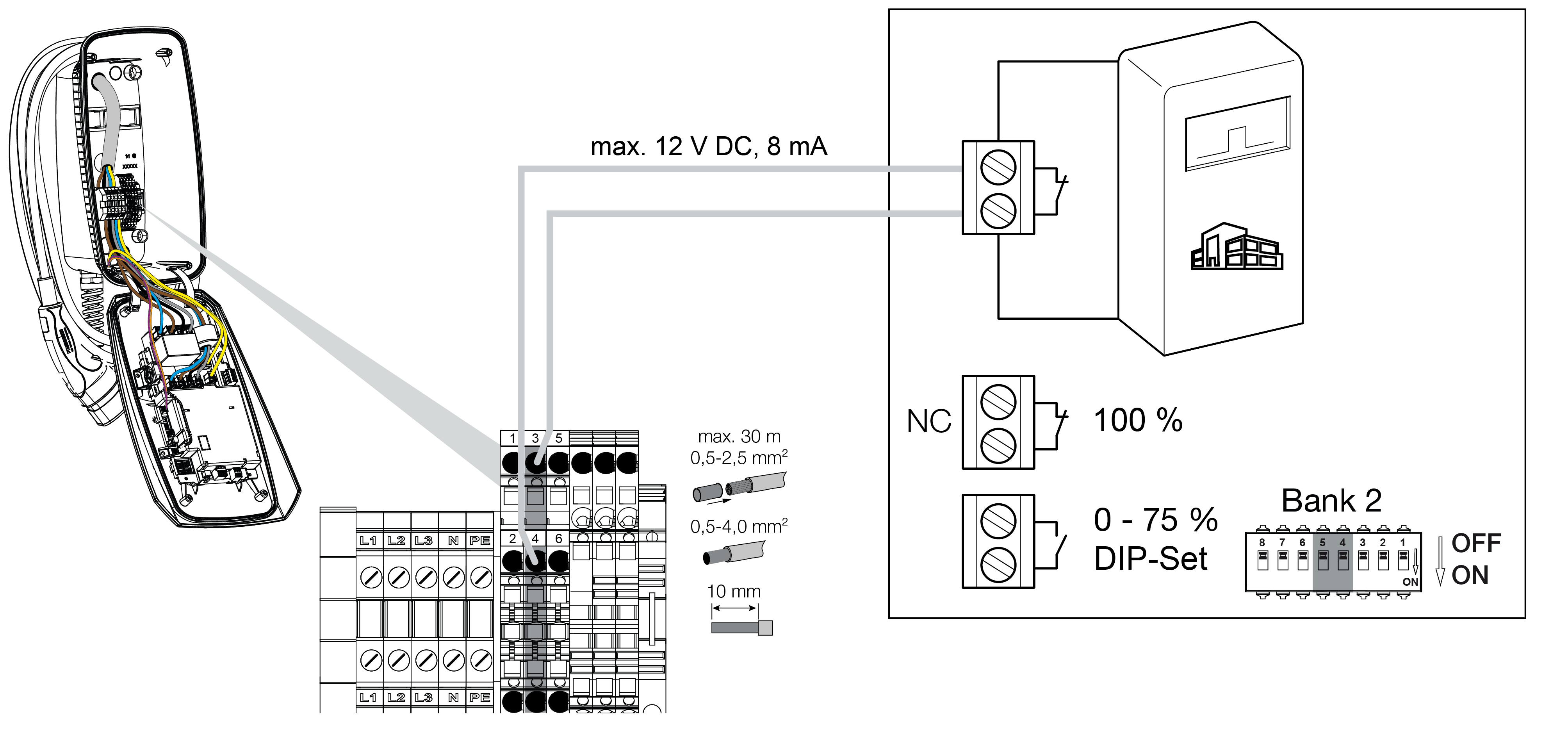
Configuration
The reduced charging current can be set using DIP switches 4 and 5 on bank S2 if the switching contact at the downgrade input is controlled (open).
The charging current is reduced as a percentage depending on the maximum set charging current.