Additional settings
The cogwheel (Settings) takes you to the additional setting options.
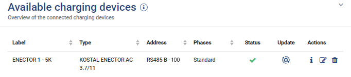
Available charging devices
This view provides an overview of the charging devices set up as well as their status.
You can also add a new charging device or update the wallbox software by going to Update.
Symbol | Explanation |
|---|---|
Name | Name of charging device |
Type | Type/model of charging device |
Address | Shows the interface on the KOSTAL Smart Energy Meter to which the charging device is connected via RS485 and the RS485 address used to set up the charging device |
Phases | Shows the current selection of phases used for charging. See also Selecting phase usage
|
| Status of charging device |
| Update: This can be used to update the charging device’s firmware. See also Updating wallbox firmware The menu item is only displayed if SW version 2021.51.9787 or higher is installed on the wallbox. |
| Info: Shows the serial number, hardware and firmware of the charging device. |
| Edit: This can be used to change the following. Name: The name of the charging device can be changed here. Serial interface: Selection of the interface on the KSEM to which the communication cable to the ENECTOR is connected. Slave address: Shows the assigned RS485 address. Phase rotation of the wallbox: Select connected phase order in the ENECTOR. This must match the physical connection, e.g. L1/L2/L3 (standard). Phases used: Selection of the phases which the charging device uses to charge the electric vehicle as standard.
|
| Delete: Delete the set-up charging device. |


Overload protection
The overload protection prevents the main fuse from tripping at the grid connection. This is configured in the wallbox via DIP switches and displayed here.
The settings can be changed here at a later date should the fuse size change. The wallbox DIP switches do not have to be adjusted as part of this process. The KOSTAL Smart Energy Meter uses the values set here to check for overload.
Parameter | Explanation |
|---|---|
Type of mains connection | Select the type of mains connection.
|
Rated current Lx | Correctly set the rated current of the main fuse per phase here. If the value set for the fuse is greater than the actual value, protection against overloading the main fuse cannot be guaranteed. The rated current of each fuse can be read off the fuse/circuit breaker in the house connection box. Example:
In this case, 35 A must be set because otherwise the smallest fuse would trip in the event of overload. |
Phase balancing
The unbalanced phase load is calculated from the greatest difference in currents between the connected phases. The Energy Manager undertakes phase balancing in order to observe the set limit value. The current consumption of controllable consumers is restricted in order to achieve this. In Germany, the maximum permitted value is 4600 VA. Please find out the maximum that applies to your country and set the maximum unbalanced phase load permitted in your country.
Advanced settings
Some electric vehicles may experience problems with low charging currents.
The 2011 CP EV out of signaled duty range ID is output as an event in the KOSTAL Smart Energy Meter.
If this happens, a higher minimum charging current can be selected to remedy the problem.
The problem occurs if a low start charging power (e.g. 6 A) has been set in the wallbox but the electric vehicle needs more power (e.g. 8 A). This results in an error in the wallbox. Increasing the minimum charging current can remedy the problem. However, this also means that all electric vehicles will always start with the increased minimum charging current as long as this setting is activated.
Minimum charging current | Set the minimum charging current per phase from 6 to 16 A. Default value 6 A. |
Recorded phase changes
Here you can download the log file (phase_switching_log.txt) for the logged phase switching.
The following aspects are recorded in the log file:
- the day and time at which the switchover took place,
- the electric vehicle connected,
- the charging device used,
- the phase usage selected (standard or single-phase).